
Gigabit Ethernet Switch User's Manual
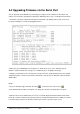
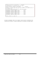
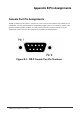
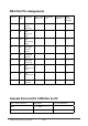
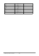
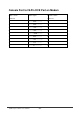
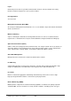
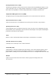
Table Of Contents
- Chapter 1. Introduction
- Chapter 2. Installing the Switch
- Chapter 3. Switch Management
- Chapter 4. Console Interface
- 4.1 Login Screen
- 4.2 Main Menu
- 4.3 System Information Menu
- 4.4 Management Setup Menu
- 4.5 Device Control Menu
- 4.5.1 Setting the System Operation Mode
- 4.5.2 Layer 2 Menu
- 4.5.3 Using the Bridge Menu
- 4.5.4 Configuring Virtual LANs
- 4.5.5 Configuring IGMP Snooping
- 4.5.6 Configuring IP Settings
- 4.5.7 Security Menu
- 4.5.8 Jumbo Packet Configuration
- 4.6 Monitoring the Switch
- 4.6.1 Displaying Port Statistics
- 4.6.2 Layer 2 Address Tables
- 4.6.3 Displaying Bridge Information
- 4.6.4 Displaying VLAN Information
- 4.6.5 IP Multicast Registration Table
- 4.6.6 IP Address Table
- 4.7 Resetting the System
- 4.8 Logging Off the System
- Chapter 5. Web Interface
- 5.1 Web-Based Configuration and Monitoring
- 5.2 Navigating the Web Browser Interface
- 5.3 Panel Display
- 5.4 Main Menu
- 5.5 System Information Menu
- 5.6 Management Setup Menu
- 5.7 Device Control Menu
- 5.7.1 Layer 2 Menu
- 5.7.2 Using the Bridge Menu
- 5.7.3 Configuring Virtual LANs
- 5.7.4 Configuring IGMP Snooping
- 5.7.5 Configuring IP Settings
- 5.7.6 Configuring Security Filters
- 5.7.7 Jumbo Packet Configuration
- 5.8 Monitoring the Switch
- 5.9 Resetting the System
- Chapter 6.Advanced Topics
- Appendix A Troubleshooting
- Appendix B Pin Assignments
- GLOSSARY

WGS3 Layer 3 Switch User’s Manual
- 253 -
DB-9 Port Pin Assignments
EIA Circuit CCITT
Signal
Description Switch’s DB9
DTE Pin #
PC DB9 DTE
Pin #
Modem DB25
DCE Pin #
Signal
Direction
DTE-DCE
CF 109 DCD (Data
Carrier
Detected)
1 1 8 <------
BB 104 RxD
(Received
Data)
3 2 3 <------
BA 1033 TxD
(Transmitted
Data)
2 3 2 ------>
CD 108 DTR (Data
Terminal
Ready)
6 4 20 ------>
AB 102 SG (Signal
Ground)
5 5 7 -------
CC 107 DSR (Data
Set Ready)
4 6 6 <------
CA 105 RTS
(Request-to-S
end)
8 7 4 ------>
CB 106 CTS
(Clear-to-Sen
d)
7
8 5 <------
CE 125 RI (Ring
Indicator)
9
9 22 <------
Console Port to 9-Pin COM Port on PC
Switch’s 9-Pin Serial Port CCITT Signal PC’s 9-Pin COM Port
1 DCD ----------- DCD ------------ 1
2 TXD ----------- RXD ----------> 2