
Gigabit Ethernet Switch User's Manual
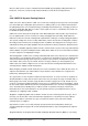
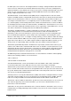
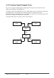
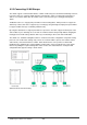
Table Of Contents
- Chapter 1. Introduction
- Chapter 2. Installing the Switch
- Chapter 3. Switch Management
- Chapter 4. Console Interface
- 4.1 Login Screen
- 4.2 Main Menu
- 4.3 System Information Menu
- 4.4 Management Setup Menu
- 4.5 Device Control Menu
- 4.5.1 Setting the System Operation Mode
- 4.5.2 Layer 2 Menu
- 4.5.3 Using the Bridge Menu
- 4.5.4 Configuring Virtual LANs
- 4.5.5 Configuring IGMP Snooping
- 4.5.6 Configuring IP Settings
- 4.5.7 Security Menu
- 4.5.8 Jumbo Packet Configuration
- 4.6 Monitoring the Switch
- 4.6.1 Displaying Port Statistics
- 4.6.2 Layer 2 Address Tables
- 4.6.3 Displaying Bridge Information
- 4.6.4 Displaying VLAN Information
- 4.6.5 IP Multicast Registration Table
- 4.6.6 IP Address Table
- 4.7 Resetting the System
- 4.8 Logging Off the System
- Chapter 5. Web Interface
- 5.1 Web-Based Configuration and Monitoring
- 5.2 Navigating the Web Browser Interface
- 5.3 Panel Display
- 5.4 Main Menu
- 5.5 System Information Menu
- 5.6 Management Setup Menu
- 5.7 Device Control Menu
- 5.7.1 Layer 2 Menu
- 5.7.2 Using the Bridge Menu
- 5.7.3 Configuring Virtual LANs
- 5.7.4 Configuring IGMP Snooping
- 5.7.5 Configuring IP Settings
- 5.7.6 Configuring Security Filters
- 5.7.7 Jumbo Packet Configuration
- 5.8 Monitoring the Switch
- 5.9 Resetting the System
- Chapter 6.Advanced Topics
- Appendix A Troubleshooting
- Appendix B Pin Assignments
- GLOSSARY

WGS3 Layer 3 Switch User’s Manual
- 242 -
6.3.3 Connecting VLAN Groups
The switch supports communication within a common VLAN using store-and-forward switching. However,
if you have devices in separate VLANs that must communicate, and it is not practical to include these
devices in a common VLAN, then the VLANs can be connected via Layer 3 routing provided by this
switch.
Traditional routers use only physical port numbers in their routing tables, which provides no support for
VLANs. By contrast, this device supports Layer 3 routing by using both logical and physical port numbers
to support VLANs and Layer 3 switching simultaneously.
By using the abstraction of a logical port number to represent a collection of physical switch ports in the
same VLAN, Layer 3 switching can occur from one VLAN to another transparently without changing the
routing protocol and IP routing software, while Layer 2 switching is still used for intra-VLAN traffic.
The switch uses standard routing tables that are constructed via static configuration or dynamic routing
protocols such as RIP. Each routing entry consists of a network address (that is, an IP address with a
subnet mask), and a virtual interface number. Each virtual interface corresponds to a virtual LAN,
identified by the VLAN ID. Also note that multiple routing entries can be provided for the same virtual
interface by adding the required routing table entries for the same virtual interface. A simple VLAN
configuration that supports routing is shown below.
VLANs Connected via IP Routing