
Gigabit Ethernet Switch User's Manual
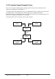
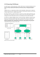
Table Of Contents
- Chapter 1. Introduction
- Chapter 2. Installing the Switch
- Chapter 3. Switch Management
- Chapter 4. Console Interface
- 4.1 Login Screen
- 4.2 Main Menu
- 4.3 System Information Menu
- 4.4 Management Setup Menu
- 4.5 Device Control Menu
- 4.5.1 Setting the System Operation Mode
- 4.5.2 Layer 2 Menu
- 4.5.3 Using the Bridge Menu
- 4.5.4 Configuring Virtual LANs
- 4.5.5 Configuring IGMP Snooping
- 4.5.6 Configuring IP Settings
- 4.5.7 Security Menu
- 4.5.8 Jumbo Packet Configuration
- 4.6 Monitoring the Switch
- 4.6.1 Displaying Port Statistics
- 4.6.2 Layer 2 Address Tables
- 4.6.3 Displaying Bridge Information
- 4.6.4 Displaying VLAN Information
- 4.6.5 IP Multicast Registration Table
- 4.6.6 IP Address Table
- 4.7 Resetting the System
- 4.8 Logging Off the System
- Chapter 5. Web Interface
- 5.1 Web-Based Configuration and Monitoring
- 5.2 Navigating the Web Browser Interface
- 5.3 Panel Display
- 5.4 Main Menu
- 5.5 System Information Menu
- 5.6 Management Setup Menu
- 5.7 Device Control Menu
- 5.7.1 Layer 2 Menu
- 5.7.2 Using the Bridge Menu
- 5.7.3 Configuring Virtual LANs
- 5.7.4 Configuring IGMP Snooping
- 5.7.5 Configuring IP Settings
- 5.7.6 Configuring Security Filters
- 5.7.7 Jumbo Packet Configuration
- 5.8 Monitoring the Switch
- 5.9 Resetting the System
- Chapter 6.Advanced Topics
- Appendix A Troubleshooting
- Appendix B Pin Assignments
- GLOSSARY

WGS3 Layer 3 Switch User’s Manual
- 238 -
To create a virtual link, you must specify an Area Border Router (ABR) and a common transit area at
both ends of the link (page 2-61 or 3-46). One ABR will border on the target area and the transit area,
while the other borders on the transit area and the backbone. The configuration on each router must
include the transit area identifier and the ABR at the other end of the link.
6.2.7 Non-IP Protocol Routing
The switch supports IP routing only. Non-IP protocols such as IPX and AppleTalk can not be routed by
this switch, and will be confined within their local VLAN group unless bridged by an external router.
To coexist with a network built on other multilayer switches, the subnetworks for non-IP protocols must
follow the same logical boundary as that of the IP subnetworks. A separate multi-protocol router can then
be used to link the subnetworks by connecting to one port from each available VLAN on the network.