
Gigabit Ethernet Switch User's Manual

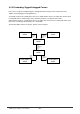
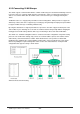
Table Of Contents
- Chapter 1. Introduction
- Chapter 2. Installing the Switch
- Chapter 3. Switch Management
- Chapter 4. Console Interface
- 4.1 Login Screen
- 4.2 Main Menu
- 4.3 System Information Menu
- 4.4 Management Setup Menu
- 4.5 Device Control Menu
- 4.5.1 Setting the System Operation Mode
- 4.5.2 Layer 2 Menu
- 4.5.3 Using the Bridge Menu
- 4.5.4 Configuring Virtual LANs
- 4.5.5 Configuring IGMP Snooping
- 4.5.6 Configuring IP Settings
- 4.5.7 Security Menu
- 4.5.8 Jumbo Packet Configuration
- 4.6 Monitoring the Switch
- 4.6.1 Displaying Port Statistics
- 4.6.2 Layer 2 Address Tables
- 4.6.3 Displaying Bridge Information
- 4.6.4 Displaying VLAN Information
- 4.6.5 IP Multicast Registration Table
- 4.6.6 IP Address Table
- 4.7 Resetting the System
- 4.8 Logging Off the System
- Chapter 5. Web Interface
- 5.1 Web-Based Configuration and Monitoring
- 5.2 Navigating the Web Browser Interface
- 5.3 Panel Display
- 5.4 Main Menu
- 5.5 System Information Menu
- 5.6 Management Setup Menu
- 5.7 Device Control Menu
- 5.7.1 Layer 2 Menu
- 5.7.2 Using the Bridge Menu
- 5.7.3 Configuring Virtual LANs
- 5.7.4 Configuring IGMP Snooping
- 5.7.5 Configuring IP Settings
- 5.7.6 Configuring Security Filters
- 5.7.7 Jumbo Packet Configuration
- 5.8 Monitoring the Switch
- 5.9 Resetting the System
- Chapter 6.Advanced Topics
- Appendix A Troubleshooting
- Appendix B Pin Assignments
- GLOSSARY

WGS3 Layer 3 Switch User’s Manual
- 233 -
6.2.2 IP Switching
IP Switching (or packet forwarding) encompasses tasks required to forward packets for both Layer 2 and
Layer 3, as well as traditional routing.
These functions include:
• Layer 2 forwarding (switching) based on the Layer 2 destination MAC address
• Layer 3 forwarding (routing):
- Based on the Layer 3 destination address
- Replacing destination/source MAC addresses for each hop
- Incrementing the hop count
- Decrementing the time-to-live
- Verifying and recalculating the Layer 3 checksum
If the destination node is on the same subnetwork as the source network, then the packet can be
transmitted directly without the help of a router.
However, if the MAC address is not yet known to the switch, an Address Resolution Protocol (ARP)
packet with the destination IP address is broadcast to get the destination MAC address from the
destination node. The IP packet can then be sent directly with the destination MAC address.
If the destination belongs to a different subnet on this switch, the packet can be routed directly to the
destination node. However, if the packet belongs to a subnet not included on this switch, then the packet
should be sent to a router (with the MAC address of the router used as the destination MAC address,
and the destination IP address of the destination node). The router will then forward the packet to the
destination node via the correct path. The router can also use the ARP protocol to find out the MAC
address of the destination node of the next router when necessary.
Note: In order to perform IP switching, the switch should be recognized by other network nodes as an IP
router, either by setting it as the default gateway, or by redirection from another router via the ICMP
process.
When the switch receives an IP packet addressed to its own MAC address, the packet follows the Layer
3 routing process. The destination IP address is checked against the Layer 3 address table. If the
address is not already there, the switch broadcasts an ARP packet to all the ports on the destination
VLAN to find out the destination MAC address. After the MAC address is discovered, the packet is
reformatted and sent out to the destination. The reformat process includes decreasing the Time-To-Live
(TTL) field of the IP header, recalculating the IP header checksum, and replacing the destination MAC
address with either the MAC address of the destination node or that of the next hop router.
When another packet destined to the same node arrives, the destination MAC can be retrieved directly
from the Layer 3 address table; the packet is then reformatted and sent out the destination port. IP
switching can be done at wire-speed when the destination address entry is already in the Layer 3
address table.