
Gigabit Ethernet Switch User's Manual
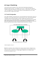
Table Of Contents
- Chapter 1. Introduction
- Chapter 2. Installing the Switch
- Chapter 3. Switch Management
- Chapter 4. Console Interface
- 4.1 Login Screen
- 4.2 Main Menu
- 4.3 System Information Menu
- 4.4 Management Setup Menu
- 4.5 Device Control Menu
- 4.5.1 Setting the System Operation Mode
- 4.5.2 Layer 2 Menu
- 4.5.3 Using the Bridge Menu
- 4.5.4 Configuring Virtual LANs
- 4.5.5 Configuring IGMP Snooping
- 4.5.6 Configuring IP Settings
- 4.5.7 Security Menu
- 4.5.8 Jumbo Packet Configuration
- 4.6 Monitoring the Switch
- 4.6.1 Displaying Port Statistics
- 4.6.2 Layer 2 Address Tables
- 4.6.3 Displaying Bridge Information
- 4.6.4 Displaying VLAN Information
- 4.6.5 IP Multicast Registration Table
- 4.6.6 IP Address Table
- 4.7 Resetting the System
- 4.8 Logging Off the System
- Chapter 5. Web Interface
- 5.1 Web-Based Configuration and Monitoring
- 5.2 Navigating the Web Browser Interface
- 5.3 Panel Display
- 5.4 Main Menu
- 5.5 System Information Menu
- 5.6 Management Setup Menu
- 5.7 Device Control Menu
- 5.7.1 Layer 2 Menu
- 5.7.2 Using the Bridge Menu
- 5.7.3 Configuring Virtual LANs
- 5.7.4 Configuring IGMP Snooping
- 5.7.5 Configuring IP Settings
- 5.7.6 Configuring Security Filters
- 5.7.7 Jumbo Packet Configuration
- 5.8 Monitoring the Switch
- 5.9 Resetting the System
- Chapter 6.Advanced Topics
- Appendix A Troubleshooting
- Appendix B Pin Assignments
- GLOSSARY
WGS3 Layer 3 Switch User’s Manual
- 232 -
6.2 Layer 3 Switching
The two major functions provided by a Layer 3 switch include IP Switching and Routing Path
Management. When the switch is set to multilayer mode, it acts as a routing switch, with support for
standard IP routing and the ability to pass traffic between VLANs as required. However, when the switch
is first set to multilayer mode, no default routing is defined. As with all traditional routers, the routing
function must first be configured to work. (RIP).
6.2.1 Initial Configuration
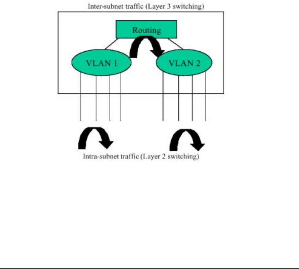
In the default configuration, all ports belong to the same virtual LAN and the switch provides only Layer 2
functionality. So you should first group all the ports that belong to the same subnet into virtual LANs. By
separating the switch into different VLANs, the network is partitioned into subnetworks that are
disconnected at Layer 2. Network traffic within the same subnet is still switched using Layer 2 switching.
And the VLANs can now be interconnected (only as required) with Layer 3 switching. Each VLAN
represents a virtual interface to Layer 3. You just need to provide the network addresses for each virtual
interface, and the traffic between different subnetworks will be routed by Layer 3 switching.
VLAN Configuration for Layer 3
Note: When operating the switch in multilayer mode, all ports should be defined as untagged, and no
VLANs can overlap. You should also assign the same default PVID to the ports at both ends of a link if
the VLAN must cross the switches. (See “VLAN Tagging” configuration.) These limitations will be
removed for future firmware versions.