
Gigabit Ethernet Switch User's Manual
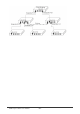
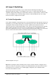
Table Of Contents
- Chapter 1. Introduction
- Chapter 2. Installing the Switch
- Chapter 3. Switch Management
- Chapter 4. Console Interface
- 4.1 Login Screen
- 4.2 Main Menu
- 4.3 System Information Menu
- 4.4 Management Setup Menu
- 4.5 Device Control Menu
- 4.5.1 Setting the System Operation Mode
- 4.5.2 Layer 2 Menu
- 4.5.3 Using the Bridge Menu
- 4.5.4 Configuring Virtual LANs
- 4.5.5 Configuring IGMP Snooping
- 4.5.6 Configuring IP Settings
- 4.5.7 Security Menu
- 4.5.8 Jumbo Packet Configuration
- 4.6 Monitoring the Switch
- 4.6.1 Displaying Port Statistics
- 4.6.2 Layer 2 Address Tables
- 4.6.3 Displaying Bridge Information
- 4.6.4 Displaying VLAN Information
- 4.6.5 IP Multicast Registration Table
- 4.6.6 IP Address Table
- 4.7 Resetting the System
- 4.8 Logging Off the System
- Chapter 5. Web Interface
- 5.1 Web-Based Configuration and Monitoring
- 5.2 Navigating the Web Browser Interface
- 5.3 Panel Display
- 5.4 Main Menu
- 5.5 System Information Menu
- 5.6 Management Setup Menu
- 5.7 Device Control Menu
- 5.7.1 Layer 2 Menu
- 5.7.2 Using the Bridge Menu
- 5.7.3 Configuring Virtual LANs
- 5.7.4 Configuring IGMP Snooping
- 5.7.5 Configuring IP Settings
- 5.7.6 Configuring Security Filters
- 5.7.7 Jumbo Packet Configuration
- 5.8 Monitoring the Switch
- 5.9 Resetting the System
- Chapter 6.Advanced Topics
- Appendix A Troubleshooting
- Appendix B Pin Assignments
- GLOSSARY

WGS3 Layer 3 Switch User’s Manual
- 230 -
6.1.2 Multicast Switching
For multicast switching, the switch checks whether the received frame is a Bridge Protocol Data Unit
(BPDU). If a BPDU is received, the switch forwards the frame for processing by the Spanning Tree
Protocol. Otherwise, the switch performs the following processes:
• VLAN classification— same as for unicast switching.
• Learning— same as for unicast switching.
• Filtering— after learning, the switch checks the same filtering criteria used for unicast switching, except
that there is no destination MAC address to check.
• Forwarding— the switch floods the received multicast frame to all ports within the VLAN, excluding the
source port. At the same time, the switch decides whether a VLAN tag needs to be added to or stripped
from the frame, depending on the VLAN tagged/untagged configuration and VLAN ID for the output port.
• Aging— same as for unicast switching.
6.1.3 Spanning Tree Algorithm
The Spanning Tree Algorithm (that is, the STA-configuration algorithm as outlined in IEEE 802.1D) can
be used to detect and disable network loops, and to provide link backup. This allows the switch to
interact with other bridging devices (including STA- compliant switches, bridges or routers) in your
network to ensure that only one route exists between any two stations on the network. If redundant paths
or loops are detected, one or more ports are put into a blocking state (stopped from forwarding packets)
to eliminate the extra paths. Moreover, if one or more of the paths in a stable spanning tree topology fail,
this algorithm will automatically change ports from blocking state to forwarding state to reestablish
contact with all network stations.
STA uses a distributed algorithm to select a bridging device (STA-compliant switch, bridge or router) that
serves as the root of the spanning tree network. It selects a root port on each bridging device (except for
the root device) which incurs the lowest path cost when forwarding a packet from that device to the root
device. Then it selects a designated bridging device from each LAN which incurs the lowest path cost
when forwarding a packet from that LAN to the root device. All ports connected to designated bridging
devices are assigned as designated ports.
After determining the lowest cost spanning tree, it enables all root ports and designated ports, and
disables all other ports. Network packets are therefore only forwarded between root ports and designated
ports, eliminating any possible network loops.
Once a stable network topology has been established, all bridges listen for Hello BPDUs (Bridge Protocol
Data Units) transmitted from the Root Bridge. If a bridge does not get a Hello BPDU after a predefined
interval (Maximum Age), the bridge assumes that the link to the Root Bridge is down. This bridge will
then initiate negotiations with other bridges to reconfigure the network to reestablish a valid network
topology.
The following figure gives an illustration of how the Spanning Tree Algorithm assigns bridging device
ports.