
Gigabit Ethernet Switch User's Manual
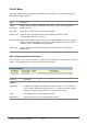
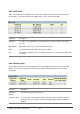
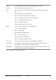
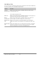
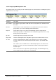
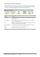
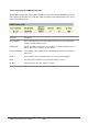
Table Of Contents
- Chapter 1. Introduction
- Chapter 2. Installing the Switch
- Chapter 3. Switch Management
- Chapter 4. Console Interface
- 4.1 Login Screen
- 4.2 Main Menu
- 4.3 System Information Menu
- 4.4 Management Setup Menu
- 4.5 Device Control Menu
- 4.5.1 Setting the System Operation Mode
- 4.5.2 Layer 2 Menu
- 4.5.3 Using the Bridge Menu
- 4.5.4 Configuring Virtual LANs
- 4.5.5 Configuring IGMP Snooping
- 4.5.6 Configuring IP Settings
- 4.5.7 Security Menu
- 4.5.8 Jumbo Packet Configuration
- 4.6 Monitoring the Switch
- 4.6.1 Displaying Port Statistics
- 4.6.2 Layer 2 Address Tables
- 4.6.3 Displaying Bridge Information
- 4.6.4 Displaying VLAN Information
- 4.6.5 IP Multicast Registration Table
- 4.6.6 IP Address Table
- 4.7 Resetting the System
- 4.8 Logging Off the System
- Chapter 5. Web Interface
- 5.1 Web-Based Configuration and Monitoring
- 5.2 Navigating the Web Browser Interface
- 5.3 Panel Display
- 5.4 Main Menu
- 5.5 System Information Menu
- 5.6 Management Setup Menu
- 5.7 Device Control Menu
- 5.7.1 Layer 2 Menu
- 5.7.2 Using the Bridge Menu
- 5.7.3 Configuring Virtual LANs
- 5.7.4 Configuring IGMP Snooping
- 5.7.5 Configuring IP Settings
- 5.7.6 Configuring Security Filters
- 5.7.7 Jumbo Packet Configuration
- 5.8 Monitoring the Switch
- 5.9 Resetting the System
- Chapter 6.Advanced Topics
- Appendix A Troubleshooting
- Appendix B Pin Assignments
- GLOSSARY
WGS3 Layer 3 Switch User’s Manual
- 222 -
5.8.6.5 OSPF Table
You can use this menu to display the OSPF router linkages for the autonomous system based on the
Link State Table, Neighbor Table, and Virtual Neighbor Table.
Parameter Description
Interface Table Displays interface OSPF status
Link State Table Displays a summary link state advertisements.
Neighbor Table Displays current neighbor routers.
Virtual Neighbor Table Displays current virtual neighbors.
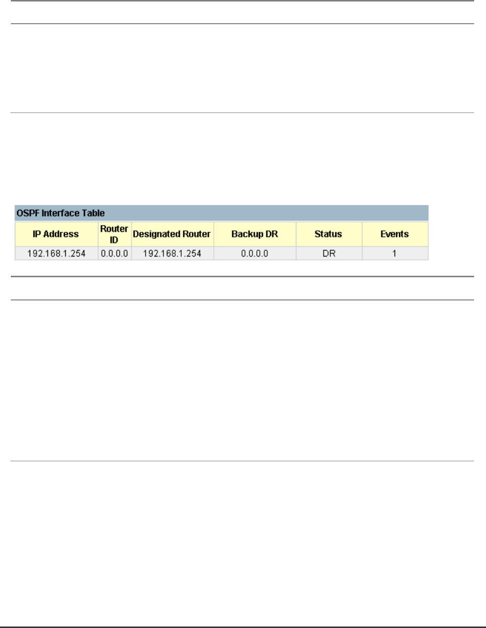
5.8.6.5.1 Display Interface Table
This function allow you to display each IP interface’s OSPF status.
Parameter Description
IP Address IP address of the interface
Rtr ID The OSPF identifier for the neighboring router.
Designated Rtr The designated router IP address for the broadcast network on the interface
Backup Rtr The backup designated router IP address for the broadcast network on the
interface
Status The interface status.
Events The number of events encountered that cause a neighbor state change since
boot up.
5.8.6.5.2 Displaying the Link State Table
The link state table displays all advertisements in the link state database. This database contains linkage
information for all the areas to which this router is attached. Note that all the routers within an area
exchange information to ensure that they maintain an identical link state database. This database can
therefore be used to troubleshoot network configuration problems.