
Gigabit Ethernet Switch User's Manual
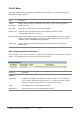
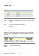
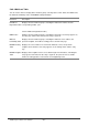
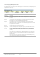
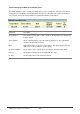
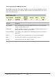
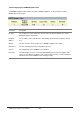
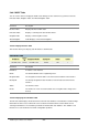
Table Of Contents
- Chapter 1. Introduction
- Chapter 2. Installing the Switch
- Chapter 3. Switch Management
- Chapter 4. Console Interface
- 4.1 Login Screen
- 4.2 Main Menu
- 4.3 System Information Menu
- 4.4 Management Setup Menu
- 4.5 Device Control Menu
- 4.5.1 Setting the System Operation Mode
- 4.5.2 Layer 2 Menu
- 4.5.3 Using the Bridge Menu
- 4.5.4 Configuring Virtual LANs
- 4.5.5 Configuring IGMP Snooping
- 4.5.6 Configuring IP Settings
- 4.5.7 Security Menu
- 4.5.8 Jumbo Packet Configuration
- 4.6 Monitoring the Switch
- 4.6.1 Displaying Port Statistics
- 4.6.2 Layer 2 Address Tables
- 4.6.3 Displaying Bridge Information
- 4.6.4 Displaying VLAN Information
- 4.6.5 IP Multicast Registration Table
- 4.6.6 IP Address Table
- 4.7 Resetting the System
- 4.8 Logging Off the System
- Chapter 5. Web Interface
- 5.1 Web-Based Configuration and Monitoring
- 5.2 Navigating the Web Browser Interface
- 5.3 Panel Display
- 5.4 Main Menu
- 5.5 System Information Menu
- 5.6 Management Setup Menu
- 5.7 Device Control Menu
- 5.7.1 Layer 2 Menu
- 5.7.2 Using the Bridge Menu
- 5.7.3 Configuring Virtual LANs
- 5.7.4 Configuring IGMP Snooping
- 5.7.5 Configuring IP Settings
- 5.7.6 Configuring Security Filters
- 5.7.7 Jumbo Packet Configuration
- 5.8 Monitoring the Switch
- 5.9 Resetting the System
- Chapter 6.Advanced Topics
- Appendix A Troubleshooting
- Appendix B Pin Assignments
- GLOSSARY
WGS3 Layer 3 Switch User’s Manual
- 215 -
5.8.6.2 ARP Table
Address Resolution Protocol (ARP) defines a method for extracting a host’s Ethernet address from its
Internet address. This table shows the IP-to-MAC address cache discovered via ARP.
Parameter Description
IP Address IP addresses for which ARP has resolved the physical address through a broadcast
message.
MAC Address MAC address that maps to the corresponding IP address.
VLAN The VLAN group to which this host has been assigned.
Port The port this to which host device is attached. (Port “0” refers to an interface defined on
this switch.)
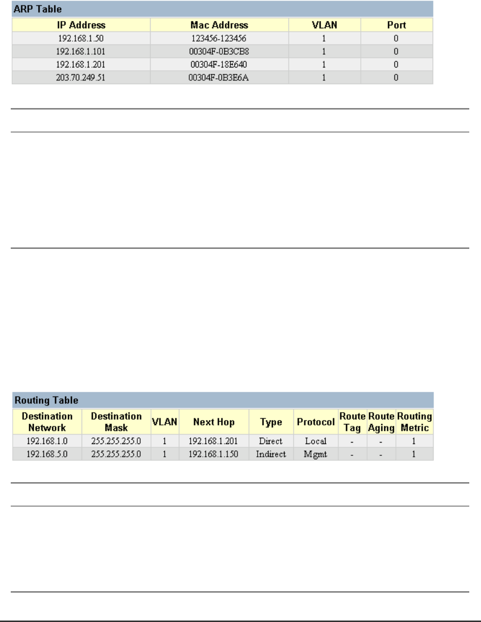
5.8.6.3 Routing Table
The Routing Table lists the routes through which all recognized Ethernet networks (and corresponding
VLANs) can be reached. This table includes all routes learned through routing protocols or manual
configuration.
Parameter Description
Destination
Network
A destination network, subnet or host.
Destination Mask The subnet mask that specifies the bits to match. A routing entry will be used for a
packet if the bits in the address set by the destination mask match the Destination
Network.