
Gigabit Ethernet Switch User's Manual
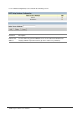
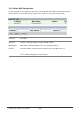
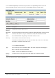
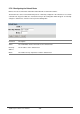
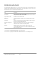
Table Of Contents
- Chapter 1. Introduction
- Chapter 2. Installing the Switch
- Chapter 3. Switch Management
- Chapter 4. Console Interface
- 4.1 Login Screen
- 4.2 Main Menu
- 4.3 System Information Menu
- 4.4 Management Setup Menu
- 4.5 Device Control Menu
- 4.5.1 Setting the System Operation Mode
- 4.5.2 Layer 2 Menu
- 4.5.3 Using the Bridge Menu
- 4.5.4 Configuring Virtual LANs
- 4.5.5 Configuring IGMP Snooping
- 4.5.6 Configuring IP Settings
- 4.5.7 Security Menu
- 4.5.8 Jumbo Packet Configuration
- 4.6 Monitoring the Switch
- 4.6.1 Displaying Port Statistics
- 4.6.2 Layer 2 Address Tables
- 4.6.3 Displaying Bridge Information
- 4.6.4 Displaying VLAN Information
- 4.6.5 IP Multicast Registration Table
- 4.6.6 IP Address Table
- 4.7 Resetting the System
- 4.8 Logging Off the System
- Chapter 5. Web Interface
- 5.1 Web-Based Configuration and Monitoring
- 5.2 Navigating the Web Browser Interface
- 5.3 Panel Display
- 5.4 Main Menu
- 5.5 System Information Menu
- 5.6 Management Setup Menu
- 5.7 Device Control Menu
- 5.7.1 Layer 2 Menu
- 5.7.2 Using the Bridge Menu
- 5.7.3 Configuring Virtual LANs
- 5.7.4 Configuring IGMP Snooping
- 5.7.5 Configuring IP Settings
- 5.7.6 Configuring Security Filters
- 5.7.7 Jumbo Packet Configuration
- 5.8 Monitoring the Switch
- 5.9 Resetting the System
- Chapter 6.Advanced Topics
- Appendix A Troubleshooting
- Appendix B Pin Assignments
- GLOSSARY
WGS3 Layer 3 Switch User’s Manual
- 197 -
5.7.5.1 Subnet Configuration). Static routes take precedence over dynamically learned routes and
remain in the table until you remove them or the corresponding IP interface from this switch.
Parameter Description
Destination
Network
A destination network, subnet or host.
Destination
Mask
The subnet mask that specifies the bits to match. A routing entry will be used for a packet
if the bits in the address set by the destination mask match the Destination Network
VLAN The VLAN within which the gateway or destination address resides.
Next Hop The IP address of the router at the next hop.
Note that the network portion of the next hop must match that used for one of the subnet
IP interfaces configured on this switch. (See “
5.7.5.1 Subnet Configuration”.)
Type The IP route type for the destination network. This switch supports the following types:
Direct - A directly connected subnetwork.
Indirect - A remote IP subnetwork or host address.
Routing
Metric*
A relative measure of the path cost from this switch to the destination network.
* This value depends on the specific routing protocol.