
Gigabit Ethernet Switch User's Manual
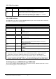
Table Of Contents
- Chapter 1. Introduction
- Chapter 2. Installing the Switch
- Chapter 3. Switch Management
- Chapter 4. Console Interface
- 4.1 Login Screen
- 4.2 Main Menu
- 4.3 System Information Menu
- 4.4 Management Setup Menu
- 4.5 Device Control Menu
- 4.5.1 Setting the System Operation Mode
- 4.5.2 Layer 2 Menu
- 4.5.3 Using the Bridge Menu
- 4.5.4 Configuring Virtual LANs
- 4.5.5 Configuring IGMP Snooping
- 4.5.6 Configuring IP Settings
- 4.5.7 Security Menu
- 4.5.8 Jumbo Packet Configuration
- 4.6 Monitoring the Switch
- 4.6.1 Displaying Port Statistics
- 4.6.2 Layer 2 Address Tables
- 4.6.3 Displaying Bridge Information
- 4.6.4 Displaying VLAN Information
- 4.6.5 IP Multicast Registration Table
- 4.6.6 IP Address Table
- 4.7 Resetting the System
- 4.8 Logging Off the System
- Chapter 5. Web Interface
- 5.1 Web-Based Configuration and Monitoring
- 5.2 Navigating the Web Browser Interface
- 5.3 Panel Display
- 5.4 Main Menu
- 5.5 System Information Menu
- 5.6 Management Setup Menu
- 5.7 Device Control Menu
- 5.7.1 Layer 2 Menu
- 5.7.2 Using the Bridge Menu
- 5.7.3 Configuring Virtual LANs
- 5.7.4 Configuring IGMP Snooping
- 5.7.5 Configuring IP Settings
- 5.7.6 Configuring Security Filters
- 5.7.7 Jumbo Packet Configuration
- 5.8 Monitoring the Switch
- 5.9 Resetting the System
- Chapter 6.Advanced Topics
- Appendix A Troubleshooting
- Appendix B Pin Assignments
- GLOSSARY

WGS3 Layer 3 Switch User’s Manual
- 10 -
NOTE: The unit supports a "hot remove" feature which permits you to connect or disconnect
twisted-pair or fiber cables without powering off the switch and without disrupting the operation
of the devices attached to the switch. However, due to the spanning tree learning process, the
new attached device may takes about 30 seconds to be able to connect the other devices.
This period can be shortened by adjusting the spanning tree configuration.
2.6 Verifying System Operation
Verify that all attached devices have a valid connection. The switch monitors the link status for each port.
If any device is properly connected to the switch and transmitting a link beat signal, the Link indicator will
light up for the corresponding port. If the Link indicator fails to light when you connect a device to the
switch, check the following items:
Be sure all network cables and connectors are properly attached to the connected device and the switch.
See if your cable is functioning properly by using it for another port and attached device that displays
valid indications when connected to the network.
Be sure no twisted-pair cable exceeds 100 meters (328 feet).