
Gigabit Ethernet Switch User's Manual
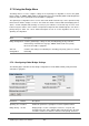
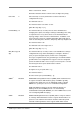
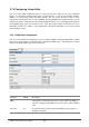
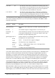
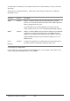
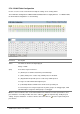
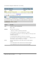
Table Of Contents
- Chapter 1. Introduction
- Chapter 2. Installing the Switch
- Chapter 3. Switch Management
- Chapter 4. Console Interface
- 4.1 Login Screen
- 4.2 Main Menu
- 4.3 System Information Menu
- 4.4 Management Setup Menu
- 4.5 Device Control Menu
- 4.5.1 Setting the System Operation Mode
- 4.5.2 Layer 2 Menu
- 4.5.3 Using the Bridge Menu
- 4.5.4 Configuring Virtual LANs
- 4.5.5 Configuring IGMP Snooping
- 4.5.6 Configuring IP Settings
- 4.5.7 Security Menu
- 4.5.8 Jumbo Packet Configuration
- 4.6 Monitoring the Switch
- 4.6.1 Displaying Port Statistics
- 4.6.2 Layer 2 Address Tables
- 4.6.3 Displaying Bridge Information
- 4.6.4 Displaying VLAN Information
- 4.6.5 IP Multicast Registration Table
- 4.6.6 IP Address Table
- 4.7 Resetting the System
- 4.8 Logging Off the System
- Chapter 5. Web Interface
- 5.1 Web-Based Configuration and Monitoring
- 5.2 Navigating the Web Browser Interface
- 5.3 Panel Display
- 5.4 Main Menu
- 5.5 System Information Menu
- 5.6 Management Setup Menu
- 5.7 Device Control Menu
- 5.7.1 Layer 2 Menu
- 5.7.2 Using the Bridge Menu
- 5.7.3 Configuring Virtual LANs
- 5.7.4 Configuring IGMP Snooping
- 5.7.5 Configuring IP Settings
- 5.7.6 Configuring Security Filters
- 5.7.7 Jumbo Packet Configuration
- 5.8 Monitoring the Switch
- 5.9 Resetting the System
- Chapter 6.Advanced Topics
- Appendix A Troubleshooting
- Appendix B Pin Assignments
- GLOSSARY
WGS3 Layer 3 Switch User’s Manual
- 168 -
5.7.3 Configuring Virtual LANs
You can use the VLAN configuration menu to assign any port on the switch to any of up to 256 LAN
groups. In conventional networks with routers, broadcast traffic is split up into separate domains.
Switches do not inherently support broadcast domains. This can lead to broadcast storms in large
networks that handle traffic such as IPX or NetBEUI. By using IEEE 802.1Q compliant VLANs, you can
organize any group of network nodes into separate broadcast domains, thus confining broadcast traffic to
the originating group. This also provides a more secure and cleaner network environment. For more
information on how to use VLANs, see “6.3 Virtual LANs”. The VLAN configuration screens are described
in the following sections.
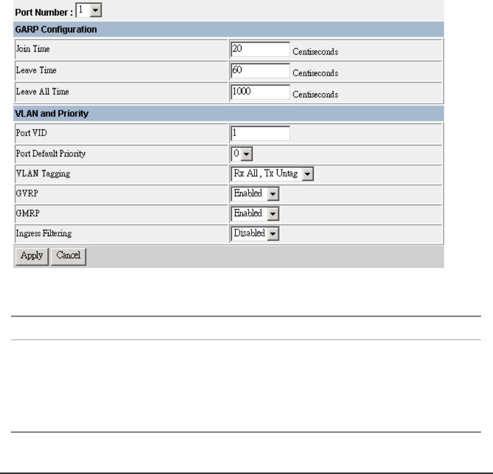
5.7.3.1 VLAN Port Configuration
You can use the VLAN Port Configuration screen to configure GARP, the default VLAN identifier, default
port priority, VLAN tagging on outgoing frames, GVRP and GMRP status, and filtering for incoming
frames for VLAN groups this port does not belong to.
Parameter Default Description
GARP
*1
Group Address Registration Protocol is used by GVRP and GMRP to
register or deregister client attributes for client services within a bridged
LAN.
Join Time 20 The interval (centiseconds) between transmitting requests/queries to
participate in a group.