
Gigabit Ethernet Switch User's Manual
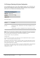

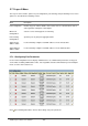
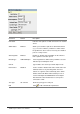


Table Of Contents
- Chapter 1. Introduction
- Chapter 2. Installing the Switch
- Chapter 3. Switch Management
- Chapter 4. Console Interface
- 4.1 Login Screen
- 4.2 Main Menu
- 4.3 System Information Menu
- 4.4 Management Setup Menu
- 4.5 Device Control Menu
- 4.5.1 Setting the System Operation Mode
- 4.5.2 Layer 2 Menu
- 4.5.3 Using the Bridge Menu
- 4.5.4 Configuring Virtual LANs
- 4.5.5 Configuring IGMP Snooping
- 4.5.6 Configuring IP Settings
- 4.5.7 Security Menu
- 4.5.8 Jumbo Packet Configuration
- 4.6 Monitoring the Switch
- 4.6.1 Displaying Port Statistics
- 4.6.2 Layer 2 Address Tables
- 4.6.3 Displaying Bridge Information
- 4.6.4 Displaying VLAN Information
- 4.6.5 IP Multicast Registration Table
- 4.6.6 IP Address Table
- 4.7 Resetting the System
- 4.8 Logging Off the System
- Chapter 5. Web Interface
- 5.1 Web-Based Configuration and Monitoring
- 5.2 Navigating the Web Browser Interface
- 5.3 Panel Display
- 5.4 Main Menu
- 5.5 System Information Menu
- 5.6 Management Setup Menu
- 5.7 Device Control Menu
- 5.7.1 Layer 2 Menu
- 5.7.2 Using the Bridge Menu
- 5.7.3 Configuring Virtual LANs
- 5.7.4 Configuring IGMP Snooping
- 5.7.5 Configuring IP Settings
- 5.7.6 Configuring Security Filters
- 5.7.7 Jumbo Packet Configuration
- 5.8 Monitoring the Switch
- 5.9 Resetting the System
- Chapter 6.Advanced Topics
- Appendix A Troubleshooting
- Appendix B Pin Assignments
- GLOSSARY

WGS3 Layer 3 Switch User’s Manual
- 159 -
5.7.1.3 Configuring Port Trunks
Ports can be combined into an aggregate link to increase the bandwidth of a network connection or
ensure fault recovery. You can configure trunks between any two switches. The ports on this switch can
be grouped into a trunk consisting of two, four or eight ports, creating an aggregate bandwidth to 400,
800, 1600, 4000 or 8000 Mbps when operating at full duplex. Besides balancing the load across each
port in the trunk, the additional ports provide redundancy by taking over the load if another port in the
trunk should fail. However, before making any physical connections between devices, use the Port
Trunking Configuration menu to specify the trunk on the devices at both ends. When using a port trunk,
remember that::
• The ports that can be assigned to the same trunk on WGS3-2620 are listed below:
Two ports as a trunk
<<13, 01>> <<14, 02>> <<15, 03>> <<16, 04>>
<<17, 05>> <<18, 06>> <<19, 07>> <<20, 08>>
<<21, 09>> <<22, 10>> <<23, 11>> <<24, 12>>
Four ports as a trunk
<<13, 01, 14, 02>> <<15, 03, 16, 04>>
<<17, 05, 18, 06>> <<19, 07, 20, 08>>
<<21, 09, 22, 10>> <<23, 11, 24, 12>>
Eight ports as a trunk
<<13, 01, 14, 02, 15, 03, 16, 04>>
<<17, 05, 18, 06, 19, 07, 20, 08>>
<<21, 09, 22, 10, 23, 11, 24, 12>>
Gigabit Ethernet Ports as a trunk
<<25, 26>>
• The ports that can be assigned to the same trunk on WGS3-404 are listed below:
Two ports as a trunk
<<1, 2>> <<3, 4>> <<5, 6>> <<7, 8>>
Four ports as a trunk
<<1, 2, 3, 4>> <<5, 6, 7, 8>>
• Ports can only be assigned to one trunk.
• The ports at both ends of a connection must be configured as trunk ports.
• The ports at both ends of a trunk must be configured in an identical manner, including
communication mode, and VLAN assignments.
• None of the ports in a trunk can be configured as a mirror or monitor port.
• All the ports in a trunk have to be treated as a whole when moved from/to, added or deleted from
a VLAN.
• The Spanning Tree Algorithm will treat all the ports in a trunk as a whole.
• Enable the trunk prior to connecting any cable between the switches to avoid creating a loop.