
Gigabit Ethernet Switch User's Manual
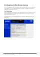
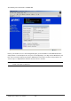
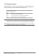
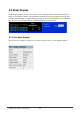
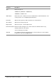
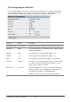
Table Of Contents
- Chapter 1. Introduction
- Chapter 2. Installing the Switch
- Chapter 3. Switch Management
- Chapter 4. Console Interface
- 4.1 Login Screen
- 4.2 Main Menu
- 4.3 System Information Menu
- 4.4 Management Setup Menu
- 4.5 Device Control Menu
- 4.5.1 Setting the System Operation Mode
- 4.5.2 Layer 2 Menu
- 4.5.3 Using the Bridge Menu
- 4.5.4 Configuring Virtual LANs
- 4.5.5 Configuring IGMP Snooping
- 4.5.6 Configuring IP Settings
- 4.5.7 Security Menu
- 4.5.8 Jumbo Packet Configuration
- 4.6 Monitoring the Switch
- 4.6.1 Displaying Port Statistics
- 4.6.2 Layer 2 Address Tables
- 4.6.3 Displaying Bridge Information
- 4.6.4 Displaying VLAN Information
- 4.6.5 IP Multicast Registration Table
- 4.6.6 IP Address Table
- 4.7 Resetting the System
- 4.8 Logging Off the System
- Chapter 5. Web Interface
- 5.1 Web-Based Configuration and Monitoring
- 5.2 Navigating the Web Browser Interface
- 5.3 Panel Display
- 5.4 Main Menu
- 5.5 System Information Menu
- 5.6 Management Setup Menu
- 5.7 Device Control Menu
- 5.7.1 Layer 2 Menu
- 5.7.2 Using the Bridge Menu
- 5.7.3 Configuring Virtual LANs
- 5.7.4 Configuring IGMP Snooping
- 5.7.5 Configuring IP Settings
- 5.7.6 Configuring Security Filters
- 5.7.7 Jumbo Packet Configuration
- 5.8 Monitoring the Switch
- 5.9 Resetting the System
- Chapter 6.Advanced Topics
- Appendix A Troubleshooting
- Appendix B Pin Assignments
- GLOSSARY
WGS3 Layer 3 Switch User’s Manual
- 142 -
5.5 System Information Menu
Use the System Information Menu to display a basic description of the switch, including contact
information, and hardware/firmware versions.
Menu Description
System Information Provides basic system description, including contact information.
Switch Information Shows hardware/firmware version numbers, power status, and expansion
modules used in the stack.
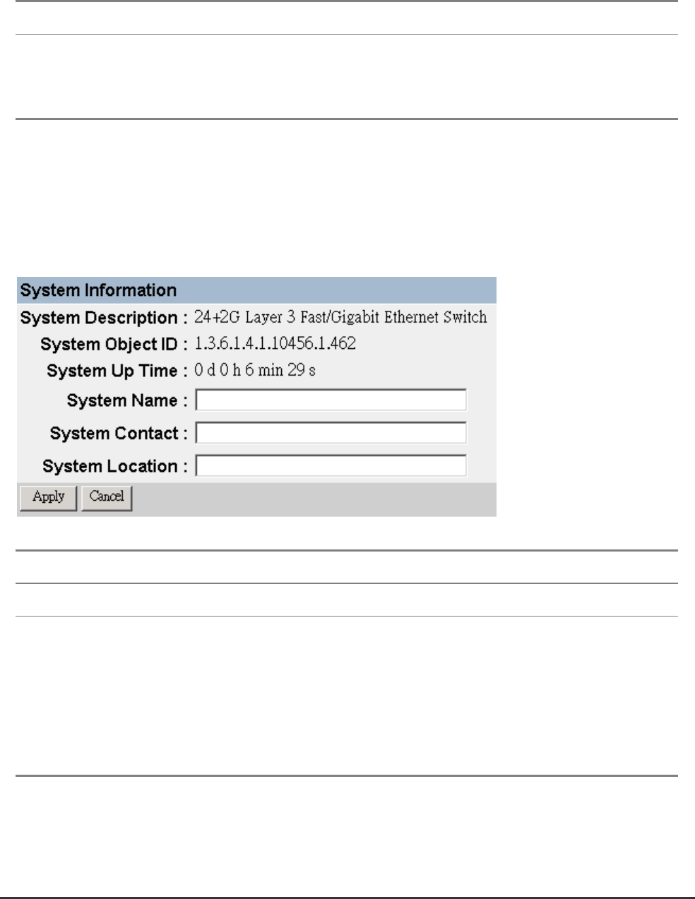
5.5.1 Displaying System Information
Use the System Information screen to display descriptive information about the switch, or for quick
system identification as shown in the following figure and table.
Parameter Description
System Description System hardware description.
System Name*. Name assigned to the switch system
Object ID MIB II object identifier for switch’ s network management subsystem.
Location* Specifies the area or location where the system resides.
Contact* Contact person for the system.
System Up Time Length of time the current management agent has been running.
* Maximum string length is 99, but the screen only displays 45 characters. You can use the arrow keys to
browse the whole string.