
Gigabit Ethernet Switch User's Manual
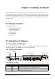
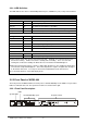
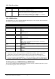
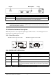
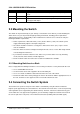
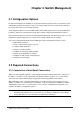
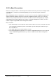
Table Of Contents
- Chapter 1. Introduction
- Chapter 2. Installing the Switch
- Chapter 3. Switch Management
- Chapter 4. Console Interface
- 4.1 Login Screen
- 4.2 Main Menu
- 4.3 System Information Menu
- 4.4 Management Setup Menu
- 4.5 Device Control Menu
- 4.5.1 Setting the System Operation Mode
- 4.5.2 Layer 2 Menu
- 4.5.3 Using the Bridge Menu
- 4.5.4 Configuring Virtual LANs
- 4.5.5 Configuring IGMP Snooping
- 4.5.6 Configuring IP Settings
- 4.5.7 Security Menu
- 4.5.8 Jumbo Packet Configuration
- 4.6 Monitoring the Switch
- 4.6.1 Displaying Port Statistics
- 4.6.2 Layer 2 Address Tables
- 4.6.3 Displaying Bridge Information
- 4.6.4 Displaying VLAN Information
- 4.6.5 IP Multicast Registration Table
- 4.6.6 IP Address Table
- 4.7 Resetting the System
- 4.8 Logging Off the System
- Chapter 5. Web Interface
- 5.1 Web-Based Configuration and Monitoring
- 5.2 Navigating the Web Browser Interface
- 5.3 Panel Display
- 5.4 Main Menu
- 5.5 System Information Menu
- 5.6 Management Setup Menu
- 5.7 Device Control Menu
- 5.7.1 Layer 2 Menu
- 5.7.2 Using the Bridge Menu
- 5.7.3 Configuring Virtual LANs
- 5.7.4 Configuring IGMP Snooping
- 5.7.5 Configuring IP Settings
- 5.7.6 Configuring Security Filters
- 5.7.7 Jumbo Packet Configuration
- 5.8 Monitoring the Switch
- 5.9 Resetting the System
- Chapter 6.Advanced Topics
- Appendix A Troubleshooting
- Appendix B Pin Assignments
- GLOSSARY
WGS3 Layer 3 Switch User’s Manual
- 7 -
Console Buzzer Button Power
Port Function
Power This is where you will connect the AC power cord. 100~240VAC is allowed.
Console This is where you will connect to the RS-232 serial port on your PC for
configuring the management function, discussed in Chapter 3.
NOTE: To depress the Buzzer button will change the reaction of the buzzer. If the button is set to on,
the buzzer will ring as the system is under the status of overheat. Set to off, the buzzer will not
work even if the system overheats.
2.2.4 Module Hardware Description
WGS3-404 provides 4 slots for optional Gigabit copper and fiber module. The following picture show
that front panel of gigabit expansion module.
2.2.4.1 Panel Description
WGSW-C1GT Module Status LEDs WGSW-C1SX Module Status LEDs
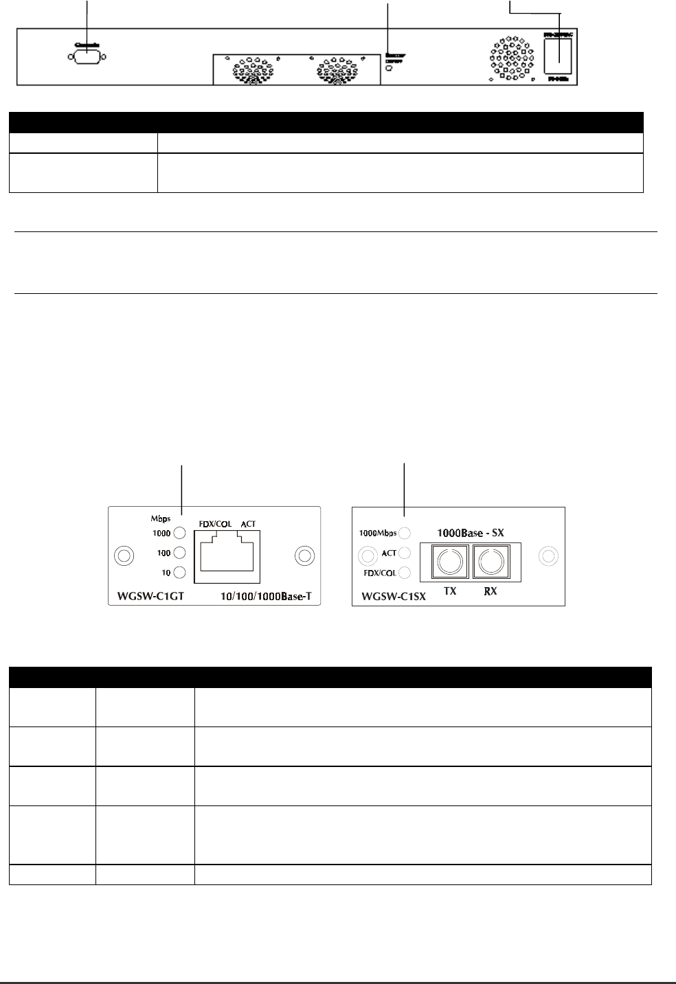
2.2.4.2 WGSW-C1GT LED Definition
LED Color Function
1000 Green Lights to indicate that the Switch is sending or receiving data at 1000
Mbps.
100 Green Lights to indicate that the Switch is sending or receiving data at 100
Mbps.
10 Yellow Lights to indicate that the Switch is sending or receiving data at 10
Mbps.
FDX/COL Yellow Lights green to indicate that the port is operating in full-duplex mode.
Blinks orange periodically to indicate that the connection is experiencing
collisions.
Act Green Lights to indicate that the connection is acting.