
Gigabit Ethernet Switch User's Manual
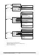
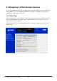
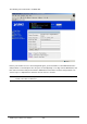
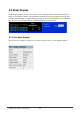
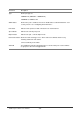
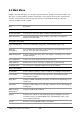
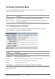
Table Of Contents
- Chapter 1. Introduction
- Chapter 2. Installing the Switch
- Chapter 3. Switch Management
- Chapter 4. Console Interface
- 4.1 Login Screen
- 4.2 Main Menu
- 4.3 System Information Menu
- 4.4 Management Setup Menu
- 4.5 Device Control Menu
- 4.5.1 Setting the System Operation Mode
- 4.5.2 Layer 2 Menu
- 4.5.3 Using the Bridge Menu
- 4.5.4 Configuring Virtual LANs
- 4.5.5 Configuring IGMP Snooping
- 4.5.6 Configuring IP Settings
- 4.5.7 Security Menu
- 4.5.8 Jumbo Packet Configuration
- 4.6 Monitoring the Switch
- 4.6.1 Displaying Port Statistics
- 4.6.2 Layer 2 Address Tables
- 4.6.3 Displaying Bridge Information
- 4.6.4 Displaying VLAN Information
- 4.6.5 IP Multicast Registration Table
- 4.6.6 IP Address Table
- 4.7 Resetting the System
- 4.8 Logging Off the System
- Chapter 5. Web Interface
- 5.1 Web-Based Configuration and Monitoring
- 5.2 Navigating the Web Browser Interface
- 5.3 Panel Display
- 5.4 Main Menu
- 5.5 System Information Menu
- 5.6 Management Setup Menu
- 5.7 Device Control Menu
- 5.7.1 Layer 2 Menu
- 5.7.2 Using the Bridge Menu
- 5.7.3 Configuring Virtual LANs
- 5.7.4 Configuring IGMP Snooping
- 5.7.5 Configuring IP Settings
- 5.7.6 Configuring Security Filters
- 5.7.7 Jumbo Packet Configuration
- 5.8 Monitoring the Switch
- 5.9 Resetting the System
- Chapter 6.Advanced Topics
- Appendix A Troubleshooting
- Appendix B Pin Assignments
- GLOSSARY

WGS3 Layer 3 Switch User’s Manual
- 141 -
Jumbo Packet Menu
*4
Allows the switch to send jumbo packet up to 9k
Network Monitor Menu
Port Statistics Displays statistics on network traffic passing through the selected port, including
information from the Interfaces Group, Ethernet-link MIB, and RMON MIB
Layer 2 Address Table Contains the unicast address table.
Bridge Menu Displays Spanning Tree information for the overall bridge and for specified ports.
VLAN Menu Displays dynamic port registration information for VLANs, as well as all VLAN
forwarding information for static and dynamic assignment.
IP Multicast
Registration Table
*1
Displays all the multicast groups active on this switch, including the multicast IP
addresses and corresponding VLANs.
IP Menu
*2
Displays all the IP subnets used on this switch, as well as the corresponding
VLANs and ports. Also contains the ARP table, routing table and multicast
table.
Restart System Menu Restarts the system with options to reload factory defaults.
1: Only displays when the WGS3-2620 is set to Layer 2 mode.
2. Only displays when WGS3-2620 is set to multilayer mode and WGS3-404..
3. Only displays when using WGS3-2620.
4. Only displays when using WGS3-404