
Gigabit Ethernet Switch User's Manual
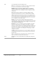

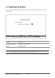
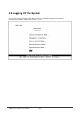
Table Of Contents
- Chapter 1. Introduction
- Chapter 2. Installing the Switch
- Chapter 3. Switch Management
- Chapter 4. Console Interface
- 4.1 Login Screen
- 4.2 Main Menu
- 4.3 System Information Menu
- 4.4 Management Setup Menu
- 4.5 Device Control Menu
- 4.5.1 Setting the System Operation Mode
- 4.5.2 Layer 2 Menu
- 4.5.3 Using the Bridge Menu
- 4.5.4 Configuring Virtual LANs
- 4.5.5 Configuring IGMP Snooping
- 4.5.6 Configuring IP Settings
- 4.5.7 Security Menu
- 4.5.8 Jumbo Packet Configuration
- 4.6 Monitoring the Switch
- 4.6.1 Displaying Port Statistics
- 4.6.2 Layer 2 Address Tables
- 4.6.3 Displaying Bridge Information
- 4.6.4 Displaying VLAN Information
- 4.6.5 IP Multicast Registration Table
- 4.6.6 IP Address Table
- 4.7 Resetting the System
- 4.8 Logging Off the System
- Chapter 5. Web Interface
- 5.1 Web-Based Configuration and Monitoring
- 5.2 Navigating the Web Browser Interface
- 5.3 Panel Display
- 5.4 Main Menu
- 5.5 System Information Menu
- 5.6 Management Setup Menu
- 5.7 Device Control Menu
- 5.7.1 Layer 2 Menu
- 5.7.2 Using the Bridge Menu
- 5.7.3 Configuring Virtual LANs
- 5.7.4 Configuring IGMP Snooping
- 5.7.5 Configuring IP Settings
- 5.7.6 Configuring Security Filters
- 5.7.7 Jumbo Packet Configuration
- 5.8 Monitoring the Switch
- 5.9 Resetting the System
- Chapter 6.Advanced Topics
- Appendix A Troubleshooting
- Appendix B Pin Assignments
- GLOSSARY

WGS3 Layer 3 Switch User’s Manual
- 132 -
Chapter 5. Web Interface
5.1 Web-Based Configuration and Monitoring
As well as the menu-driven system configuration program, this switch provides an embedded HTTP Web
agent. Using a Web browser you can configure the switch and view statistics to monitor network activity.
The Web agent can be accessed by any computer on the network using Internet Explorer 4.0 or above
Web browser.
NOTE: Current firmware version does not support Netscape Navigator.
Prior to accessing the switch from a Web browser, be sure you have first performed the following tasks:
1. Configure it with a valid IP address, subnet mask, and default gateway (for Layer 2 mode) using an
out-of-band serial connection. Provide a default gateway for Layer 2 operation of WGS3-2620 or a
default route for WGS3-2620 multilayer operation and WGS3-404 (see 4.5.6.5 Configuring the Default
Route).
2. Set a user name and password using an out-of-band serial connection( see 4.4.4 User Login
Configuration). Access to the Web agent is controlled by the same user name and password as the
on-board configuration program.
NOTE: If the path between your management station and this switch does not pass through any device
that uses the Spanning Tree Algorithm, then you can set the switch port attached to your
management station to Fast Forwarding (see 4.5.3.2 Configuring STA for Ports) to improve the
switch’s response time to management commands issued through the Web interface.
After you enter the user name and password, you will have access to the system configuration program
illustrated by the following menu hierarchy: