
Gigabit Ethernet Switch User's Manual
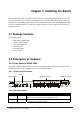
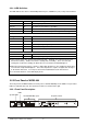
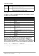
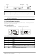
Table Of Contents
- Chapter 1. Introduction
- Chapter 2. Installing the Switch
- Chapter 3. Switch Management
- Chapter 4. Console Interface
- 4.1 Login Screen
- 4.2 Main Menu
- 4.3 System Information Menu
- 4.4 Management Setup Menu
- 4.5 Device Control Menu
- 4.5.1 Setting the System Operation Mode
- 4.5.2 Layer 2 Menu
- 4.5.3 Using the Bridge Menu
- 4.5.4 Configuring Virtual LANs
- 4.5.5 Configuring IGMP Snooping
- 4.5.6 Configuring IP Settings
- 4.5.7 Security Menu
- 4.5.8 Jumbo Packet Configuration
- 4.6 Monitoring the Switch
- 4.6.1 Displaying Port Statistics
- 4.6.2 Layer 2 Address Tables
- 4.6.3 Displaying Bridge Information
- 4.6.4 Displaying VLAN Information
- 4.6.5 IP Multicast Registration Table
- 4.6.6 IP Address Table
- 4.7 Resetting the System
- 4.8 Logging Off the System
- Chapter 5. Web Interface
- 5.1 Web-Based Configuration and Monitoring
- 5.2 Navigating the Web Browser Interface
- 5.3 Panel Display
- 5.4 Main Menu
- 5.5 System Information Menu
- 5.6 Management Setup Menu
- 5.7 Device Control Menu
- 5.7.1 Layer 2 Menu
- 5.7.2 Using the Bridge Menu
- 5.7.3 Configuring Virtual LANs
- 5.7.4 Configuring IGMP Snooping
- 5.7.5 Configuring IP Settings
- 5.7.6 Configuring Security Filters
- 5.7.7 Jumbo Packet Configuration
- 5.8 Monitoring the Switch
- 5.9 Resetting the System
- Chapter 6.Advanced Topics
- Appendix A Troubleshooting
- Appendix B Pin Assignments
- GLOSSARY

WGS3 Layer 3 Switch User’s Manual
- 6 -
2.2.2.2 Port Description
Ports # of Ports Description
10/100/1000 4 These RJ-45 ports support network speeds of 10, 100 or 1000 Mbps,
and can operate in full-duplex modes.
Expansion
Ports
4 These ports provide for the installation of one or two expansion
modules that establish a Fast or Gigabit Ethernet connection.
Note: You may install an 1000Base-SX or 1000Base-T expansion
module and use fiber optic or category 5 cabling.
2.2.2.3 LED Definition
The LEDs indicate the status of 10/100/1000 Mbps Ethernet ports, Over Heat, Fan Failure and Power.
The LEDs are explained in the following tables.
LED Color Indication
System
Power Green Lights to indicate switch is receiving power.
Fan Failure
*1
Red Lights to indicate one of the fans is failed and standby fan is
running
Over Heat
*2
Red Lights to indicate the internal temperature is equal to or higher
than 60 degree C
10/100/1000 Ports
Act Green Lights to indicate the Switch is actively receiving or sending the
data over the port.
FDX/COL Yellow Lights green to indicate that the port is operating in full-duplex
mode.
Blinks orange periodically to indicate that the connection is
experiencing collisions.
1000 Green Lights to indicate that the Switch is sending or receiving data at
1000 Mbps.
100 Green Lights to indicate that the Switch is sending or receiving data at
100 Mbps.
10 Yellow Lights to indicate that the Switch is sending or receiving data at
10 Mbps.
*1 There are two 4-inch fans and one 2-inch fan in the unit. Normally, one of the 4-inch fans and
2-inch fan is running. Another 4-inch fan is standby and not working. Once one of the two
running fans is failed, the standby fan will be drove to run and the Fan LED will light on.
*2 When the internal temperature is equal to or higher than 60 degree C, the standby fan will be
drove to run and the Temp LED will light on. Once the temperature is equal to or higher than 70
degree C, the buzzer will sound. You can press the buzzer On/Off button to turn off the buzzer.
2.2.3 Rear Panel of WGS3-2620 and WGS3-404
The rear panel of WGS3-2620 and WGS3-404 has a power connector, a Buzzer button and a console
port. The following picture shows their rear panel.