
Gigabit Ethernet Switch User's Manual
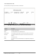

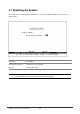
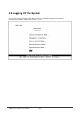
Table Of Contents
- Chapter 1. Introduction
- Chapter 2. Installing the Switch
- Chapter 3. Switch Management
- Chapter 4. Console Interface
- 4.1 Login Screen
- 4.2 Main Menu
- 4.3 System Information Menu
- 4.4 Management Setup Menu
- 4.5 Device Control Menu
- 4.5.1 Setting the System Operation Mode
- 4.5.2 Layer 2 Menu
- 4.5.3 Using the Bridge Menu
- 4.5.4 Configuring Virtual LANs
- 4.5.5 Configuring IGMP Snooping
- 4.5.6 Configuring IP Settings
- 4.5.7 Security Menu
- 4.5.8 Jumbo Packet Configuration
- 4.6 Monitoring the Switch
- 4.6.1 Displaying Port Statistics
- 4.6.2 Layer 2 Address Tables
- 4.6.3 Displaying Bridge Information
- 4.6.4 Displaying VLAN Information
- 4.6.5 IP Multicast Registration Table
- 4.6.6 IP Address Table
- 4.7 Resetting the System
- 4.8 Logging Off the System
- Chapter 5. Web Interface
- 5.1 Web-Based Configuration and Monitoring
- 5.2 Navigating the Web Browser Interface
- 5.3 Panel Display
- 5.4 Main Menu
- 5.5 System Information Menu
- 5.6 Management Setup Menu
- 5.7 Device Control Menu
- 5.7.1 Layer 2 Menu
- 5.7.2 Using the Bridge Menu
- 5.7.3 Configuring Virtual LANs
- 5.7.4 Configuring IGMP Snooping
- 5.7.5 Configuring IP Settings
- 5.7.6 Configuring Security Filters
- 5.7.7 Jumbo Packet Configuration
- 5.8 Monitoring the Switch
- 5.9 Resetting the System
- Chapter 6.Advanced Topics
- Appendix A Troubleshooting
- Appendix B Pin Assignments
- GLOSSARY

WGS3 Layer 3 Switch User’s Manual
- 127 -
State The communication state for two adjacent routers:
Down: This is the initial state of a neighbor conversation. It indicates that there
has been no recent information received from the neighbor.
Attempt: This state is only valid for neighbors attached to non-broadcast
networks. It indicates that no recent information has been received from the
neighbor, but that the router is attempting to contact the neighbor by sending
Hello packets.
Init: A Hello packet has recently been seen from the neighbor. However,
bidirectional communication has not yet been established with the neighbor.
2-Way: Communication between the two routers has been established. This is
the most advanced state short of beginning adjacency establishment. Note that
both the Designated Router and Backup Designated Router are selected from
the set of neighbors in state 2-Way or greater.
ExStart: This is the first step in creating an adjacency between the two
neighboring routers. The goal of this step is to decide which router is the master,
and to decide upon the initial sequence number. Neighbor conversations in this
state or greater are called adjacencies.
Exchange: The router is describing its entire link state database by sending
database description packets to the neighbor. (Each database description
packet has a sequence number, and is explicitly acknowledged.) All adjacencies
in Exchange state or greater are used by the flooding procedure. In fact, these
adjacencies are fully capable of transmitting and receiving all types of OSPF
routing protocol packets.
Loading: Link State Request packets are sent to the neighbor asking for more
recent advertisements that have been discovered (but not yet received) in the
Exchange state.
Full: The neighboring routers are fully adjacent. These adjacencies will now
appear in router links and network links advertisements.
Events The number of events encountered that cause a neighbor state change since
boot up.