
Gigabit Ethernet Switch User's Manual
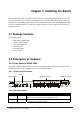
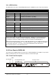
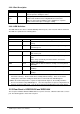
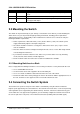
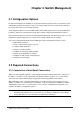
Table Of Contents
- Chapter 1. Introduction
- Chapter 2. Installing the Switch
- Chapter 3. Switch Management
- Chapter 4. Console Interface
- 4.1 Login Screen
- 4.2 Main Menu
- 4.3 System Information Menu
- 4.4 Management Setup Menu
- 4.5 Device Control Menu
- 4.5.1 Setting the System Operation Mode
- 4.5.2 Layer 2 Menu
- 4.5.3 Using the Bridge Menu
- 4.5.4 Configuring Virtual LANs
- 4.5.5 Configuring IGMP Snooping
- 4.5.6 Configuring IP Settings
- 4.5.7 Security Menu
- 4.5.8 Jumbo Packet Configuration
- 4.6 Monitoring the Switch
- 4.6.1 Displaying Port Statistics
- 4.6.2 Layer 2 Address Tables
- 4.6.3 Displaying Bridge Information
- 4.6.4 Displaying VLAN Information
- 4.6.5 IP Multicast Registration Table
- 4.6.6 IP Address Table
- 4.7 Resetting the System
- 4.8 Logging Off the System
- Chapter 5. Web Interface
- 5.1 Web-Based Configuration and Monitoring
- 5.2 Navigating the Web Browser Interface
- 5.3 Panel Display
- 5.4 Main Menu
- 5.5 System Information Menu
- 5.6 Management Setup Menu
- 5.7 Device Control Menu
- 5.7.1 Layer 2 Menu
- 5.7.2 Using the Bridge Menu
- 5.7.3 Configuring Virtual LANs
- 5.7.4 Configuring IGMP Snooping
- 5.7.5 Configuring IP Settings
- 5.7.6 Configuring Security Filters
- 5.7.7 Jumbo Packet Configuration
- 5.8 Monitoring the Switch
- 5.9 Resetting the System
- Chapter 6.Advanced Topics
- Appendix A Troubleshooting
- Appendix B Pin Assignments
- GLOSSARY
WGS3 Layer 3 Switch User’s Manual
- 5 -
2.2.1.3 LED Definition
The LEDs indicate the status of 10/100 Mbps Ethernet ports, 1000Base-T ports, Temp. Fan and Power.
LED State Indication
System
Power On Switch is receiving power.
SNMP On SNMP agent operational.
Console On RS-232 Console interface is operating
Fan
*1
On One of the fans is failed and standby fan is running
Temp
*2
On The internal temperature is equal to or higher than 60 degree C
10BaseT/100BaseTX Ports
LNK On Port has established a valid network connection
Mode
*3
COL On Collision occurs on the port
ACT On Traffic is passing through the port
FDX On Been set to full duplex
100M On Connected on 100M speed
1000BaseT Ports
LNK On Port has established a valid network connection
ACT On Traffic is passing through the port
*1 There are two 4-inch fans and one 2-inch fan in the unit. Normally, one of the 4-inch fans and
2-inch fan is running. Another 4-inch fan is standby and not working. Once one of the two
running fans is failed, the standby fan will be drove to run and the Fan LED will light on.
*2 When the internal temperature is equal to or higher than 60 degree C, the standby fan will be drove
to run and the Temp LED will light on. Once the temperature is equal to or higher than 70 degree
C, the buzzer will sound. You can press the buzzer On/Off button to turn off the buzzer.
*3 Use the Mode button to select LED display mode.
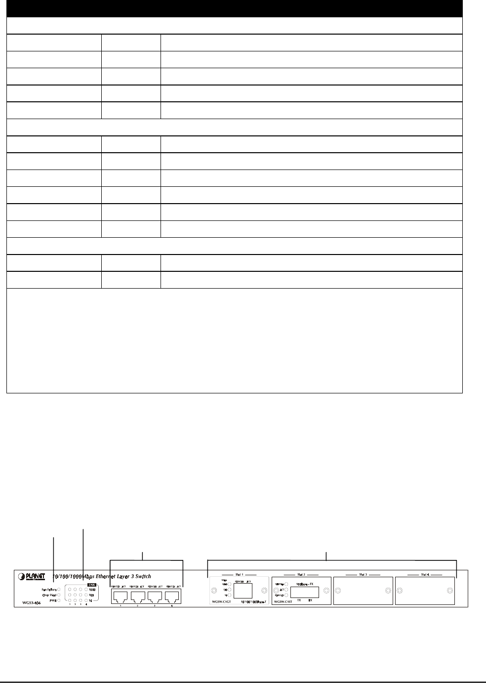
2.2.2 Front Panel of WGS3-404
The front panel of the WGS3-404 has 4 RJ-45 ports for 10/100/1000 Mbps in the middle. The port status
LEDs are indicated at the left. The expansion modules are situated at the right.
2.2.2.1 Front Panel Description
LEDs
System LEDs
10/100/1000 Mbps ports Expansion Ports