
User Manual
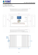
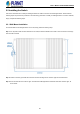

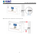

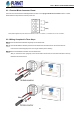
Table Of Contents
- 1. INTRODUCTION
- 2. INSTALLATION
- 3. SWITCH MANAGEMENT
- 4. WEB CONFIGURATION
- 4.1 Main Web Page
- 4.2 System
- 4.2.1 Management
- 4.2.1.1 System Information
- 4.2.1.2 IP Configuration
- 4.2.1.3 IP Status
- 4.2.1.4 Users Configuration
- 4.2.1.5 Privilege Levels
- 4.2.1.6 NTP Configuration
- 4.2.1.6.1 System Time Correction Manually
- 4.2.1.7 Time Configuration
- 4.2.1.8 UPnP
- 4.2.1.9 DHCP Relay
- 4.2.1.10 DHCP Relay Statistics
- 4.2.1.11 CPU Load
- 4.2.1.12 System Log
- 4.2.1.13 Detailed Log
- 4.2.1.14 Remote Syslog
- 4.2.1.15 SMTP Configuration
- 4.2.1.16 Fault Alarm
- 4.2.2 Simple Network Management Protocol
- 4.2.3 RMON
- 4.2.4 DHCP server
- 4.2.5 Remote Management
- 4.2.6 LCD
- 4.2.1 Management
- 4.3 Switching
- 4.3.1 Port Management
- 4.3.2 Link Aggregation
- 4.3.3 VLAN
- 4.3.3.1 VLAN Overview
- 4.3.3.2 IEEE 802.1Q VLAN
- 4.3.3.3 VLAN Port Configuration
- 4.3.3.4 VLAN Membership Status
- 4.3.3.5 VLAN Port Status
- 4.3.3.6 Private VLAN
- 4.3.3.6 Port Isolation
- 4.3.3.7 VLAN setting example:
- 4.3.3.7.1 Two Separate 802.1Q VLANs
- 4.3.3.7.2 VLAN Trunking between two 802.1Q aware switches
- 4.3.3.7.3 Port Isolate
- 4.3.3.8 MAC-based VLAN
- 4.3.3.9 IP Subnet-based VLAN Membership Configuration
- 4.3.3.10 Protocol-based VLAN
- 4.3.3.11 Protocol-based VLAN Membership
- 4.3.4 Spanning Tree Protocol
- 4.3.5 Multicast
- 4.3.6 MLD Snooping
- 4.3.7 MVR (Multicast VLAN Registration)
- 4.3.8 LLDP
- 4.3.9 MAC Address Table
- 4.3.10 Loop Protection
- 4.3.11 UDLD
- 4.3.12 GVRP
- 4.3.13 PTP
- 4.3.14 Link OAM
- 4.4 Quality of Service
- 4.5 Security
- 4.6 Ring
- 4.7 Maintenance
- 4.8 Power over Ethernet
- 4.9 ONVIF
- 5. SWITCH OPERATION
- 6. TROUBLESHOOTING
- APPENDIX A: Networking Connection
- APPENDIX B : GLOSSARY

User’s Manual of WGS-5225-8UP2SV
35
2.2 Installing the Switch
This section describes how to install your Managed Switch and make connections to the Managed Switch. Please read the
following topics and perform the procedures in the order being presented. To install your Managed Switch on a wall or cabinate,
simply complete the following steps.
2.2.1 Wall Mount Installation
To install the Wall-mount Managed Switch on the wall, simply follow the following steps:
Step 1: It is required 4 holes with 8mm diameter on the wall; the distance between the 2 holes is 230 mm and the line through
them must be horizontal.
Step 2: Install a conductor pipe inside the board hole and flush the edge of the conductor pipe with the wall surface.
Step 3: Screw the bolts into the conductor pipe. The Wall-mount Managed Switch is between bolts and conductor pipe, as
shown below.