
User Manual


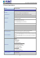

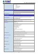

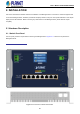
Table Of Contents
- 1. INTRODUCTION
- 2. INSTALLATION
- 3. SWITCH MANAGEMENT
- 4. WEB CONFIGURATION
- 4.1 Main Web Page
- 4.2 System
- 4.2.1 Management
- 4.2.1.1 System Information
- 4.2.1.2 IP Configuration
- 4.2.1.3 IP Status
- 4.2.1.4 Users Configuration
- 4.2.1.5 Privilege Levels
- 4.2.1.6 NTP Configuration
- 4.2.1.6.1 System Time Correction Manually
- 4.2.1.7 Time Configuration
- 4.2.1.8 UPnP
- 4.2.1.9 DHCP Relay
- 4.2.1.10 DHCP Relay Statistics
- 4.2.1.11 CPU Load
- 4.2.1.12 System Log
- 4.2.1.13 Detailed Log
- 4.2.1.14 Remote Syslog
- 4.2.1.15 SMTP Configuration
- 4.2.1.16 Fault Alarm
- 4.2.2 Simple Network Management Protocol
- 4.2.3 RMON
- 4.2.4 DHCP server
- 4.2.5 Remote Management
- 4.2.6 LCD
- 4.2.1 Management
- 4.3 Switching
- 4.3.1 Port Management
- 4.3.2 Link Aggregation
- 4.3.3 VLAN
- 4.3.3.1 VLAN Overview
- 4.3.3.2 IEEE 802.1Q VLAN
- 4.3.3.3 VLAN Port Configuration
- 4.3.3.4 VLAN Membership Status
- 4.3.3.5 VLAN Port Status
- 4.3.3.6 Private VLAN
- 4.3.3.6 Port Isolation
- 4.3.3.7 VLAN setting example:
- 4.3.3.7.1 Two Separate 802.1Q VLANs
- 4.3.3.7.2 VLAN Trunking between two 802.1Q aware switches
- 4.3.3.7.3 Port Isolate
- 4.3.3.8 MAC-based VLAN
- 4.3.3.9 IP Subnet-based VLAN Membership Configuration
- 4.3.3.10 Protocol-based VLAN
- 4.3.3.11 Protocol-based VLAN Membership
- 4.3.4 Spanning Tree Protocol
- 4.3.5 Multicast
- 4.3.6 MLD Snooping
- 4.3.7 MVR (Multicast VLAN Registration)
- 4.3.8 LLDP
- 4.3.9 MAC Address Table
- 4.3.10 Loop Protection
- 4.3.11 UDLD
- 4.3.12 GVRP
- 4.3.13 PTP
- 4.3.14 Link OAM
- 4.4 Quality of Service
- 4.5 Security
- 4.6 Ring
- 4.7 Maintenance
- 4.8 Power over Ethernet
- 4.9 ONVIF
- 5. SWITCH OPERATION
- 6. TROUBLESHOOTING
- APPENDIX A: Networking Connection
- APPENDIX B : GLOSSARY

User’s Manual of WGS-5225-8UP2SV
25
1.5 Product Specifications
Product WGS-5225-8UP2SV
Hardware Specifications
Copper Ports
8 10/100/1000BASE-T RJ45 auto-MDI/MDI-X ports
SFP Slots
2 100/1000/2500BASE-X SFP interfaces
Compatible with 100BASE-FX and 2500BASE-X SFP
PoE Injector Port
8 ports with 802.3bt PoE++ injector function with Port-1 to Port-8
RAM
128MBytes
Flash Memory
64MBytes
Reset Button
< 5 sec: System reboot
> 5 sec: Factory Default
Connector
4-pin terminal block for power input
- Pin 1/2 for Power 1 (Pin 1: V+ / Pin 2: V-)
- Pin 3/4 for Power 2 (Pin 3: V+ / Pin 4: V-)
2-pin terminal block for event alarm
Alarm
One relay output for power failure. Alarm Relay current carry ability: 1A @ 24V DC
Enclosure
IP30 aluminum case
Installation
Wall-mount
Dimensions (W x D x H)
245 x 36 x 140 mm
Weight
1,299g
Power Requirements
48~54V DC (>52V DC for PoE++ and PoE+ output recommended)
Dual power input is required for maximum power loading
Power Consumption
Max. 14.72 watts/50.23 7BTU@50V DC input (Power on without any connection)
Max. 375 watts/1280BTU@Single 54V DC input (Full loading with 360 watts PoE
function)
Max. 752 watts/2566BTU@Dual 54V DC input (Full loading with 720 watts PoE
function)
ESD Protection
6KV DC
LED Indicator
System:
PWR 1(Green)
PWR 2 (Green)
Ring (Green)
Ring Owner (Green)
Per 10/100/1000T RJ45 PoE++ Ports:
802.3bt PoE-in-Use (Green)
802.3af/at PoE-in-Use (Amber)
1000 LNK/ACT (Green)
10/100 LNK/ACT (Amber)
Per SFP Interface:
100 LNK/ACT (Amber)
1000/2500 LNK/ACT (Green)
Switching Specifications
Switch Architecture
Store-and-Forward
Switch Fabric
26Gbps/non-blocking