Industrial Wall-mount Managed Gigabit Ethernet Switch WGS-5225-8T2SV WGS-5225-8P2SV WGS-5225-8P2S Quick Installation Guide
Table of Contents 1. Package Contents........................................................................................ 3 2. Requirements.............................................................................................. 4 3. Wiring the Power Inputs............................................................................... 5 3.1 Terminal Block Connector Pinout............................................................ 6 4. Installation..................................................
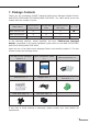
1. Package Contents Thank you for purchasing PLANET Industrial Wall-mount Managed Gigabit Switch, WGS-5225-8T2SV/WGS-5225-8P2SV/WGS-5225-8P2S. The table below shows the models with the number of ports: Model Name 10/100/1000T Copper Ports 802.3at PoE Ports 100/1000/2500X SFP Ports WGS-5225-8T2SV 8 - 2 WGS-5225-8P2SV 8 8 2 WGS-5225-8P2S 8 8 2 - 2.
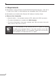
2. Requirements zz Workstations running Windows XP/2003/2008/2012/Vista/7/8/10/11, MAC OS X or later, Linux, UNIX, or other platforms are compatible with TCP/IP protocols. zz Workstations are installed with Ethernet NIC (Network Interface Card). zz Ethernet Port Connection Network cables -- Use standard network (UTP) cables with RJ45 connectors. The above Workstations is installed with Web browser.
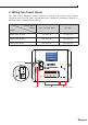
3. Wiring the Power Inputs The Wall-mount Managed Switch features a strong dual power input system (Terminal block and DC jack) incorporated into customer’s automated network to enhance system reliability and uptime. Power Input Range 3-pin Terminal Block DC Jack WGS-5225-8T2SV 12~48V DC 12~48V DC WGS-5225-8P2SV 48~56V DC 48~56V DC WGS-5225-8P2S 48~56V DC 48~56V DC Model Smart LCD 3-pin Terminal Block Ground Ring V+ PWR R.O.
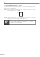
3.1 Terminal Block Connector Pinout To install the 3-pin Terminal Block Connector on the Wall-mount Managed Switch, simply follow the following steps: Step 1: Insert positive DC power wire into V+, negative DC power wire into V-, and grounding wire into Ground. Ground VV+ Step 2: Tighten the wire-clamp screws for preventing the wires from loosening and plug them into the Wall-mount Managed switch. 1. The wire gauge should be in the range from 12 to 24 AWG. Note 6 2. The device must be grounded.
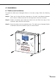
4. Installation 4.1 Wall-mount Installation To install the Wall-mount Managed Switch on the wall, simply follow the following steps: Step 1: There are 4 holes with 8mm diameter on the wall; the distance between the 2 holes is 165mm and the line through them must be horizontal. Step 2: Install a conductor pipe inside the board hole and flush the edge of the conductor pipe with the wall surface. Step 3: Screw the bolts into the conductor pipe.
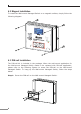
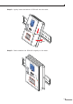
4.2 Magnet Installation To install the Wall-mount Managed Switch on a magnetic surface, simply follow the following diagram: Gro und Gro und Smart LCD V+V+ Ring DC Inpu DC Inpu t Ran t Ran gege 48-5 48-5 6V6V , 6A max . PoE+ Fib er Manag ed Magne WGS-52 25-8P2S t Mount V ing 2 4 PWR R.O. SYS SFP 1000 6 100 8 9 10 LNK LNK ACT ACT LNK/ACT PoE In-us e 1 3 5 7 PoE 9 SFP 10 4.3 DIN-rail Installation The DIN-rail kit is included in the package.
Step 2: Lightly insert the bottom of DIN-rail into the track. GrouGround nd SmSmarart LC t LCDD V+ V+ Po PoE+E+ Fib er DC DC48In Input Ra pu 48-56 -56Vt Ra,ng6Ae nge V max. W Fiber WGSGS-5225-8P -5225- 2SV 8P2SV 2 2 4 4 Ring Ring MMananagaged ed MMagne agnett Mou Mountnting ing 6 R. R.O.O.
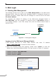
5. Web Login 5.1 Starting Web Management The following shows how to start up the Web Management of the Wall-mount Managed Switch. Note the Wall-mount Managed Switch is configured through an Ethernet connection. Please make sure the manager PC must be set to the same IP subnet address. For example, the default IP address of the Wall-mount Managed Switch is 192.168.0.100, then the manager PC should be set to 192.168.0.x (where x is a number between 1 and 254, except 100) and the default subnet mask is 255.
3. After entering the password, the main screen appears as Figure 5-3 shows. Note The following web screen is based on the WGS-5225-8P2S. The display of the WGS-5225-8P2S is the same as those of the WGS5225-8T2SV and WGS-5225-8P2SV. Figure 5-3: Web Main Screen of Wall-mount Managed Switch The Switch Menu on the top of the Web page lets you access all the commands and statistics the Wall-mount Managed Switch provides.
Figure 5-5: Switch Menu Now, you can use the Web management interface to continue the Switch management. Please refer to the user’s manual for more. 5.2 Saving Configuration via Web To save all applied changes and set the current configuration as a startup configuration on the Web user interface, the startup-configuration file will be loaded automatically across a system reboot. 1. Click the Save icon on the top Switch Menu bar. 2. Press the “Save Configuration” button. 3.
6. SSH Login The Wall-mount Managed Switch also supports SSHv2 for remote management. The Wall-mount Managed Switch asks for user name and password for remote login when using SSHv2; please use “admin” for both username and password. Default IP address: 192.168.0.100 Username: admin Password: admin Figure 6-1: Wall-mount Managed Switch SSHv2 Login Screen The user can now enter commands to manage the Wall-mount Managed Switch.
6.1 Configuring IP Address The Wall-mount Managed Switch is shipped with default IP address shown below: IP Address: 192.168.0.100 Subnet Mask: 255.255.255.0 To check the current IP address or modify a new IP address for the Wall-mount Managed Switch, please use the procedure as follows: Display of the Current IP Address 1. At the “#” prompt, enter “show ip interface brief”. 2. The screen displays the current IP address shown in Figure 6-2.
6.2 Storing the Current Switch Configuration At the “#” prompt, enter the following command and press . # copy running-config startup-config Figure 6-3: Saving Current Configuration Command Screen If the IP is successfully configured, the Wall-mount Managed Switch will apply the new IP address setting immediately. You can access the Web interface of the Wallmount Managed Switch through the new IP address.
7. Recovering Back to Default Configuration IP Address has been changed or admin password has been forgotten – To reset the IP address to the default IP address “192.168.0.100” or reset the login password to default value, press the reset button on the front panel for about 5 seconds. After the device is rebooted, you can log in to the Web interface management within the same subnet of 192.168.0.xx.
8. LCD Touch Screen The WGS-5225-8P2SV and WGS-5225-8T2SV have a 2.4-inch color LCD touch screen with management functions. Tap the LCD touch screen to wake the LCD touch screen. Figure 8-1: To wake the LCD touch screen The factory default LCD configurations are shown as follows.
You can use the Web management interface and click LCD, and then in the LCD Management, change LCD configuration. Please refer to the user’s manual for more.
9. Customer Support Thank you for purchasing PLANET products. You can browse our online FAQs resource and User’s Manual on PLANET Web site first to check if it could solve your issue. If you need more support information, please contact PLANET switch support team. PLANET online FAQs: http://www.planet.com.tw/en/support/faq Switch support team mail address: support@planet.com.tw WGS-5225-8T2SV/WGS-5225-8P2SV/WGS-5225-8P2S User’s Manual: https://www.planet.com.