Wired / Wireless / PoE CMOS IP Camera ICA-107 ICA-107W ICA-107P User’s Manual Version: 1.
Copyright © 2007 by PLANET Technology Corp. All rights reserved. No part of this publication may be reproduced, transmitted, transcribed, stored in a retrieval system, or translated into any language or computer language, in any form or by any means, electronic, mechanical, magnetic, optical, chemical, manual or otherwise, without the prior written permission of PLANET.
R&TTE Compliance Statement This equipment complies with all the requirements of DIRECTIVE 1999/5/CE OF THE EUROPEAN PARLIAMENT AND THE COUNCIL OF 9 March 1999 on radio equipment and telecommunication terminal Equipment and the mutual recognition of their conformity (R&TTE) The R&TTE Directive repeals and replaces in the directive 98/13/EEC (Telecommunications Terminal Equipment and Satellite Earth Station Equipment) As of April 8,2000.
Contents 1. 2. 3. 4. Introduction.......................................................................................................... 1 Package Content ................................................................................................. 2 System Requirement ........................................................................................... 3 Hardware Installation........................................................................................... 4 4.1. LED and Focusing ...
7.8.3. Status ...........................................................................................................44 7.8.4. General ........................................................................................................46 7.8.5. About ...........................................................................................................47 7.9. Playback ..................................................................................................................48 7.10.
1. Introduction Searching for a powerful and economical Internet Camera? PLANET is glad to introduce our ICA-107 / ICA-107W / ICA-107P. Those Internet Cameras Integrated a microcomputer and a high quality CMOS digital-Image-Sensor, enabling it to display high quality live streaming video over your LAN and the Internet. The motion detection of the ICA-107 series can notify users via email or ftp when detecting any movement.
2. Package Content Internet Camera Power Adapter Camera Stand Kit Category 5 Ethernet Cable Quick Installation Guide CD-Rom External Antenna (ICA-107W only) If any of the above items are missing, please contact your supplier.
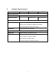
3. System Requirement Model ICA-107 ICA-107W ICA-107P Network Environment Network Access 10/ 100Base-TX Ethernet Additional Interface - IEEE 802.11b/g IEEE 802.3af PoE Monitoring System Recommendation System Hardware • CPU: Pentium 4, 1.6GHz or above • Memory Size: 256 MB (512 MB Recommended) • VGA card resolution: 800 x 600 or above Web Browser • Internet Explorer 6.
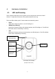
4. Hardware Installation 4.1. LED and Focusing The IP Camera head and its focus ring allow you to modify the aim and focus of the IP Camera. To adjust the IP Camera’s focus, please rotate the focus ring. There are LEDs indicating the IP Camera status and networking status. y Power When the IP Camera is power on, the LED will light on. y WLAN (ICA-107W only) When the IP Camera is linking with wireless interface, the LED will light on. This LED will flash when video is transmitting or receiving.
4.2. y Hardware Connection Power Input The DC power input connector is located on the IP Camera's bottom panel, and is labeled 12V DC with a single jack socket to supply power to the IP Camera. Power will be generated when the power supply is connected to a wall outlet. y Ethernet Jack The IP Camera's bottom panel features an RJ-45 connector for connections to 10Base-T Ethernet cabling or 100Base-TX Fast Ethernet cabling (which should be Category 5 twisted-pair cable).
Installation Procedure 1. Unpack the package and verify that all the items listed in the Chapter 2 are available. 2. Connect the IP Camera to your network with the attached network cable; please connect the IP camera to your network switch or router. 3. Connect the power adapter to IP Camera and plug the power adapter to power outlet. The IP Camera will be powered on. When the IP Camera is ready, the Power LED will light on. 4. Make sure that you have installed the ActiveX utility.
5. Software Installation Follow the steps below to install the utilities. The following installation is implemented in Windows XP and the installation procedure is similar to Windows 2000. 1. Insert the CD shipped along with the IP Camera into your CD-ROM drive. The installation page should open with your default browser. If not, please double click on the “default.htm” in the CD. 2. Click on the hyperlink “Install Administrator Utility”.
3. After clicking on the “Install Administrator Utility” hyperlink, the browser should prompt to download the installation program. Click on the “Run” button, the installation program should be started. 4. Click “Next” to start the installation.
5. Click on the “Change” button to choose the destination you wished to install the utility. If no specific requirement, leave the default setting and click “Next”. 6. Click “Install” to start installing the utility.
7. The system will install the program automatically. 8. Click “Finish” to complete the software installation.
9. After the installation, IP Camera Admin will launch automatically. It will start to search the IP Cameras in your intranet and it will list all the available IP Cameras on the camera list. Choose the one that you would like to configure and click “Setting Wizard” to processed. Camera list 10. Please enter the default password “Admin” and click “OK” to login to the IP Camera’s setup page.
11. To let the IP Camera work, you should configure the IP Camera’s IP address as you want. The utility will try to find an available IP address and recommend you using that address. Besides work with the recommended IP, you may input the IP address manually. Please be aware that the IP address of the IP Camera must be in the same IP segment of your . Click “Finish” to apply the configuration. 12. After press “Finish”, the camera will restart. Please wait for a minute.
6. Using the IP Camera Admin The IP Camera Admin allows users to search and setup the cameras located within the Intranet. With the IP Camera Admin, users can view all the information about the selected IP Camera; furthermore, it provides a setting wizard, which can guide users to add the IP Camera to the network easily and promptly. There are two ways to run the IP Camera Admin: 1. Click “Start”, select “Programs”→“IP Camera” →”Admin Utility” to run the utility. 2.
6.1. General Setting LAN Auto Discover The IP Camera Admin will search all the available IP Camera within the network when you click on this button. Camera List The name and setting status of the IP Camera will show in this list. The “ ” icon means the configuration of the IP Camera is in the status of factory default. The “ ” icon means the IP Camera has been configured before. The “ ” icon means the camera is unknown.
setting, etc. Camera Setting Detail Setting You might use this function for further configuring the IP Camera, such as IP address, Resolution, password and firmware upgrade, etc. Setting Wizard You might use this function to configure the camera name, IP address and the video port of the IP Camera.
6.2. Detail Setting After clicking on the “Detail Setting”, the IP Camera Admin will ask you to enter the “Administrator Name” and “Password” for authentication. The default administrator name / password are: Administrator Name: “Admin” Password: “Admin” After entering the password and clicking on the “OK” button, you could start to configure your IP Camera.
6.2.1. Network Setting Network Setting DHCP Enable or disable the DHCP function here. Camera Name It is recommended to name a meaningful name for the camera. For example, “Living Room”, “Front Door”. That will help you to recognize the IP Camera more easily. IP Address Please assign an available IP address to your IP Camera. Subnet Mask Please input the subnet mask that you want to use here. Gateway Please input the gateway that you want to use here.
dedicated port to access the web page, for example: http://192.168.0.20:8080. 6.2.2. Wireless Settings (ICA-107W Only) 10F Planet The IP Camera Admin will find available wireless network automatically. You could also press the “Refresh” button to find the available wireless network manually. After refresh procedure, there will show the available wireless networks.
10F Planet You might press “Connect” for connecting to the AP directly or “Add to Profile” to configure the security setting of the wireless network. 10F Planet ICA-107W supports WEP (Open System/Shared Key), WPA-PSK, WPA2-PSK and WPANone. Please select the responding security setting of the desired wireless network. After set the profile, you might remove the LAN cable, and the IP Camera will connect to the AP automatically.
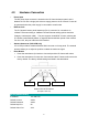
LED Status Diagram Wired Setting Environment Wireless Setting Environment a.) You should configure the wireless settings via the wired connection when you first time to set the ICA-107W to wireless interface. b.) After the configuration is done, you might remove the cable then the wireless connection should start automatically.
6.2.3. E-Mail Setting E-Mail Setting Recipient E-Mail Address You can snapshot a picture and send the picture by E-Mail. Enter the E-Mail Account for receiving the picture. SMTP Server Enter the SMTP Server for the E-Mail sending. Sender E-Mail Address Specified the e-mail address of sender. Authentication Enable or Disable the SMTP Authentication function Username When E-Mail Authentication is enabled, please input the SMTP Username here.
6.2.4. PPPoE Settings PPPoE Settings Enable/Disable Enable or Disable the PPPoE connection here. Username Enter the Username of your PPPoE account. Password Enter the Password of your PPPoE account. MTU Maximum Transmission Unit (MTU) is the largest frame that could be transmitted through the PPPoE connection. The MTU is specified in octets (eight-bit bytes). If there is no other request, please leave it as default value.
6.2.5. FTP Settings FTP Settings FTP Server The IP Camera could upload picture to the FTP server when you enable the motion detection function. Please enter the IP address of the FTP server that you want to use. FTP Port Please enter the FTP port number that your FTP server uses. In most case, the FTP server should use TCP port 21. User Name Specify the user account of ftp server. Password Specify the password of your ftp account.
6.2.6. Date / Time Settings Date / Time Settings Set Date/Time manually Set the current Date and Time here. NTP Server Enable or Disable the NTP client here. Time Zone Select your time zone here. NTP Server Specify the IP address of the NTP server.
6.2.7. Resolution Resolution Resolution You might select the desired video resolution here. Available resolutions are: 176 x 144, 320 x 240, 640 x 480.
6.2.8. Advanced Setting Advanced Setting UPnP Enable or Disable UPnP here. Enable/Disable DDNS Enable or disable DDNS function of the IP Camera. Provider The IP Camera supports the service from DynDNS, for further information, please refer to: http://www.dyndns.org Domain Name The domain name given by DynDNS is “registername.dyndns.com”. Please enter the domain name that you register for the IP Camera from DynDNS web site. Account Enter the login name for the DDNS service.
6.2.9. Users Users Administrator Setting the password of Administrator account Current Password Enter the current password of the IP Camera. New Password Enter the new password you want to use for the IP Camera. Confirm New Password Retype the new password to confirm the setting. User You might Enable/Disable the user accounts and setting the user name and password here. The IP Camera could support up to 4 user accounts.
6.2.10. Tools Tools Firmware Version Display current firmware version. Firmware Update You could upgrade IP Camera’s firmware via this function. Press this button and select the correct firmware to upgrade. Reset to Default If you want to reset the IP Camera to factory default, you might click on this button. The default settings of the IP Camera are as follows. Camera Name: “ICA-107(W / P)” IP Address: “192.168.0.20” Subnet Mask: 255.255.255.
Web Port: “80” LED Light ON/OFF You might turn all the IP Camera’s LEDs ON/OFF via this button. It can let the people don’t know this camera is monitoring. 6.2.11. About About Administrator Utility Display current Administrator Utility Version.
6.3. Setting Wizard When you click the “Setting Wizard”, the IP Camera Admin will ask you to enter the “Administrator Name” and “Password”. The default value is as follows. Administrator Name: “Admin” Password: “Admin" If the name and password you entered are correct, you can start to setup the camera. Network Setting Camera Name It is recommended to name a meaningful name for the camera. For example, “Living Room”, “Front Door”. That will help you to recognize the IP Camera more easily.
Gateway Please input the gateway that you want to use here. DNS Server Please input the desired DNS server here. After you finish the camera setting, the IP Camera Admin will ask if you want to start the IP Camera Viewer. You could click on “Ok” to run the IP Camera Viewer immediately or click on “Cancel” to run the IP Camera Viewer later.
7. Using the Camera Viewer The IP Camera Viewer allows users to view video up to four IP Cameras at the same time. It also allows users to manual/schedule recording video and playback the video file. The status of cameras such as frame rate, video received, and etc are also displayed on the screen at the same time. There are three ways to run the IP Camera Viewer: 1. Click “Start”, select “Programs”→”IP Camera”→”Camera Viewer” to run the utility. 2.
7.1. Introduction to the Control Panel When you start the IP Camera Viewer, you would see a Control Panel and the Viewer window.
7.2. Camera Buttons Camera Buttons Camera Please click on one of these number buttons for connecting to the selected IP Camera. If you want to remove the camera from the IP Camera Viewer, please right click on the icon and select “Reset Camera x”. If you want to modify the channel setting, please right click the icon and select “Configure Camera x”.
7.3. Camera Status Above the Number button, there are status bars that will indicate the different status of the IP Camera. Please refer to the table below to check the status of your IP Camera. Camera Status Yellow The channel has not been configured yet. Blue The IP Camera is connected and playing the live video. Pink The IP Camera is not connected now. Red The IP Camera is recording. 7.4.
resume the video display. Forward Clicking on the “Forward” button to forward the speed when you play the recording file. Snapshot Clicking on the “Snapshot” button will make the IP Camera Viewer to take a snapshot of the video and save the picture as a bitmap file in the hard disk. (You will learn how to set the directory for storing these bitmap files at the Section 7.8.4) Record By clicking “Record” button you can record video immediately.
7.5. Video Recording The IP Camera Viewer allows you to record the video in the “.AVI” files. There are two ways of video recording – Manual Recording and Schedule Recording. Manual Recording You can manually record the video stream into an assigned video file. Click “Record”, then the IP Camera Viewer will start to record the video stream. You can assign the path in the setting dialog.(please see section 7.8.4) Clicking “Stop” will stop recording.
7.6. Change Resolution The IP Camera Viewer supports two resolutions, 640x480 (VGA) and 320x240 (CIF). You can change the resolution of each IP Camera by clicking the resolution button. Note: Before changing the resolution of the IP Camera, you have to select the IP Camera by clicking the camera button first. If you change the resolution of an IP Camera, other clients who are viewing the same IP Camera will also see the video with the changed resolution.
7.7. View Four Cameras Simultaneously Click the four division button can view the 4 IP Cameras simultaneously in a four-division window.
7.8. Viewer Utility Setting Click the “Setting” button , the setting window of the IP Camera will pop up. Note: If you want to change the settings such as IP Address, Video Port, etc. in the “Setting” option, you must disconnect the Internet Camera first. You might disconnect the IP Camera by clicking on the “Stop” button.
7.8.1. Setting Setting Name It is not required to fill the name of IP Camera for connecting. It is for users to identify the camera. IP Address Enter the IP address of the IP Camera you want to connect here. Video Port Enter the port number of the video streaming used by the IP Camera here. Model Select the Model Name of the IP Camera. Username The user name for login into the IP Camera. By default, the user name is “Admin”. Password The password for login into the IP Camera.
7.8.2. Recording The IP Camera Viewer support schedule recording function. The IP Camera Viewer will record the video stream in the assigned file folder according to the schedule automatically. The recorded video files are AVI format. Note: 1. The IP Camera Viewer will only start to record the video stream when it is running and is successfully connecting to the Internet camera in the beginning of the schedule. 2.
One-Time Schedule Weekly Schedule Schedule New Click “New” to add a new recording schedule. Edit Select an existing schedule in the schedule list and click “Edit” to edit the schedule. Delete Select an existing schedule in the schedule list and click “Delete” to delete the schedule. Schedule Cycle Recording Check this check box to enable cycle recording.
automatically record the video stream only during the period of time. The default time is 2 minutes later from the current time. Weekly Schedule You can select the days in a week and set a period of time that you want to record the video stream. 7.8.3. Status You can see the current status of the connection session between the IP Camera Viewer and the IP Camera. Status Connected “Yes”: When the IP Camera Viewer is connecting to the IP Camera. “No”: When the utility is not connecting to the IP Camera.
Camera Viewer and the IP Camera. Video Received The total size (Unit is KByte) of video stream received from the IP Camera. Audio Received (Reserved for future use.) Frame Rate The fps (frames per second) of the current video stream. Data Rate The data rate (KByte per second) of the current video stream. Number of Frames The total number of video frames received during the current connection session between the IP Camera Viewer and the IP Camera.
7.8.4. General You can manage storage usage for the IP Camera here. General Snap Shot Directory This function lets you assign the directory where snapshot image will be stored. The default folder is where the IP Camera Viewer is installed, for example: “C:\Program Files\Internet Camera”. Record Directory This function lets you assign the directory where the recorded video files stored. The default folder is where the IP Camera Viewer is installed, for example: “C:\Program Files\Internet Camera”.
7.8.5. About About Camera Viewer Utility Display current version of IP Camera Viewer.
7.9. Playback Click the “Open File” and the “Load File” window will be popped up. Select the file that you want to play. The IP Camera Viewer will start to play the selected video file.
Playing Control Play When the video playback is in Stop state, click on the “Play” button and the IP Camera Viewer will play the video file from the beginning point. When the video playback is in Pause state, click on the “Play” button and the IP Camera Viewer will play the video file from the current pause point. When the IP Camera Viewer is playing with fast speed, just click “Play” button to let the IP Camera Viewer play with the normal speed.
to continue playing from the current pause point, just click “Play”. Stop When the IP Camera Viewer is playing, you can click “Stop” to stop the playback. If you want the IP Camera Viewer to play again, just click “Play” and the IP Camera Viewer will play the video file from the beginning point. Playing Control Forward If you want the IP Camera Viewer to play the video file in a faster speed, just click “Forward” and the IP Camera Viewer will double the playing speed.
7.10. Rotate Video Rotate function lets you rotate the video frame 180 of degree each time you click the “Rotate” . With this function, you can view the live video with normal position or rotate with 180 degree.
8. Web Connection and Setup You can use the Web browser to connect the IP Camera for viewing or setting. Open the web browser and enter the IP address of the IP Camera to establish a connection. The default IP address of the camera is “192.168.0.20”. When the welcome screen appears, enter the “Administrator Name” and “Password”. The default values are: Administrator Name: “Admin” Password: “Admin” When the IP Camera is connected, the browser will take you to the live video page.
After installed the ActiveX plug-in, the video image will be shown up in the web screen directly. (Example on ICA-107W) The menu options for the web control screen are as follows. Camera – View live video and adjust the video format from the menu. LAN – Configure the LAN port. WLAN – Configure the WLAN port. (ICA-107W Only) E-Mail & FTP – Setup the E-Mail client and FTP client.
Motion Detection – Configure the Motion Detection here. System – Configure the system settings here. Status – Shows the camera information and current status in this page. Users – The IP Camera support up to 4 user accounts. You can set those accounts here.
8.1. Camera Setting (Example on ICA-107W) Camera Setting Resolution Select the desired video resolution. Available resolutions are: 640 x 480, 320 x 240, and 176 x 144. The default resolution is CIF. Image Quality Adjust the video quality here. Max Frame Rate Set the video max frame rate. This camera can support at most 30 frames per second. Frequency Adjust this property to fitting light frequency. Brightness You can adjust the brightness of the video. This value can be from 1 to 100.
from 1 to 100. Whiteness You can adjust the white balance by change this value. This value can be from 10 to 30. Enable Auto Exposure You can enable Auto Exposure by check this box. IF this function is enabled, the Brightness, Contrast, Saturation, Hue and Whiteness adjustment would not take effect. Apply When you finish the setting, click this button to validate the setting values.
8.2. LAN Setting (Example on ICA-107W) LAN Network Type The IP Camera can obtain IP via DHCP protocol or specified a static IP Address to it. IP Address Enter an available IP Address within the range in your LAN. Subnet Mask The Subnet Mask field must match the subnet setting on your LAN. For example: 255.255.255.0. Gateway Please enter the default gateway of your LAN here. DNS Server Please enter your prefer DNS server here.
Web Port The IP Camera support web connection, the default web port is 80. If you change the web port from 80 to other port, such as 8080, you must type http://192.168.0.20:8080 to connect the camera through the web browser. Apply When you finish the “LAN” configuration, click “Apply” to apply the setting. PPPoE Enable PPPoE Enable or disable PPPoE function of the IP Camera. User Name Enter the User Name for the PPPoE account. Password Enter the Password for the PPPoE account.
8.3. WLAN (ICA-107W Only) (Example on ICA-107W) Wireless Setting Wireless connection Enable or disable the wireless function of the IP Camera. By default, the function is disabled. Network Type Infrastructure – This operation mode requires the presence of a Wireless LAN Access Point or Router. All communication is done via the Access Point or Router. Ad-Hoc – Select this mode if you want to connect to another wireless stations in the Wireless LAN network without through an Access Point or Router.
SSID The SSID (up to 32 printable ASCII characters) is the unique name identified in a WLAN. The ID prevents the unintentional merging of two co-located WLANs. You may specify a SSID for the IP Camera and then only the device with the same SSID can interconnect to the IP Camera. Channel This setting is only available for Ad Hoc mode. Select the number of the radio channel used for the networking. Basic Rate The IP Camera will force to the data rate that you selected to transmit data.
8.4. E-Mail and FTP The “E-Mail & FTP” lets you setup E-Mail client and FTP client that camera can sent image to your e-mail account or FTP server when Motion has been detected. (Example on ICA-107W) Email & FTP Recipient E-Mail Address The IP Camera supports “Motion Detection” function. Enter the E-Mail Account for receiving the alert mail. SMTP Server Enter the SMTP Server for sending the E-Mail. Sender E-Mail Address Specified the e-mail address of the e-mail sender.
to test if your setting is correct. FTP Server The IP Camera supports “Motion Detection” function. When Motion Detection event occurred, you can record the pictures to FTP server. Enter the FTP address for uploading the pictures. FTP Port Enter the FTP port that the FTP server uses. User Name Specify the user account of ftp server. Password Specify the password of your ftp account. Remote Folder Specify the folder of the ftp site that you want to store the image.
8.5. Motion Detection The “Motion Detection” allows users to setup the behavior of motion detection feature. (Example on ICA-107W) Motion Detection Motion Detection Enable Enable or Disable the Motion Detection Function. Next Event Detected Setup the interval between two events. For example, if you setup Interval the interval to 5 seconds, the next event will start after this event finished + 5 seconds. Threshold Setup the sensitivity of motion detection.
8.6. System The “System” allows users to setup the IP Camera’s parameters, like camera name, data/time setting. And also provide firmware upgrade and reset tools at this page. (Example on ICA-107W) System Camera Name The default camera name is “ICA-107(W / P)”. It is recommended to name a meaningful name for the IP Camera. Password Enter the password for the default account. The password should be 4 digits. Confirm Password Enter the password again to confirm the setting.
Upgrade Firmware You can upgrade the IP Camera’s firmware via this function. Press the browse button, find the correct firmware and press upgrade. Reset to Factory Defaults If you want to reset all the settings to factory default, please use this function to fulfill your task. Reboot Device To reboot the IP Camera, click “Reboot”. LED Setting If you wan to secure the IP Camera from noticing, you can turn off the LED light by clicking “LED Light OFF”.
8.7. Status The “Status” shows the current firmware version, uptime, system time and IP information of this camera.
8.8. Users The “Users” allows you to add four user accounts which are able to view video from the IP Camera Viewer and Web Management. These users, unlike Administrator, are not allowed to configure the IP Camera. (Example on ICA-107W) User 1 / 2 / 3 / 4 User # Login Password Confirm Password Apply Enable or Disable the user number #. Enter the login name of the user account. Enter up to 4 digits password for the new user account. Enter the password again to confirm the setting.
8.9. Log The “Log” allows users to monitor the device event and time. If you have trouble to use this device, the log file will help administrator to know the status of device. (Example on ICA-107W) Log Log screen Refresh The screen will show event and event time of device. You can press “Refresh” button to refresh the log screen.
9. Technical Specifications Video specification Max Resolution: 640 x 480 pixels Sensor: 300K pixels 1/4" color CMOS sensor Gain control: Automatic Exposure: Automatic White Balance: Automatic Lens: Manual Focus, F=1.8 Image (Video Setting) Image compression: MJPEG Image Video Digital 24-bit Color Frame rate: Up to 30fps Video resolution: 176 x 144, 320x240, 640x480 System Hardware LAN Connector: One RJ-45 port to connect to 10/100Mbps Ethernet Wireless: IEEE 802.11b/g(ICA-107W Only) PoE: 802.
10. Appendix A Router/Gateway Setup for Internet Viewing To view IP Camera across the Internet, you have to make sure Router/Gateway has configured to pass incoming TCP/UDP connections from remote PC to the IP Camera. The Router/Gateway should set port forwarding or virtual server for the connections. Please see the illustration as below. Router/Gateway Port Forwarding/Virtual Server Setup Name Protocol Port LAN IP Setup 1 TCP 80 192.168.0.20 Setup 2 TCP 4321 192.168.0.
configured Setup2.
11. Appendix B Viewing via UPnP in Windows XP When the UPnP function is enabled, the camera can be detected by UPnP compliant system such as Windows XP. The camera will be displayed in My Network Place, so you can double click the camera or right click the camera and select “Invoke” to view the video through web browser.
Enable UPnP in Windows XP SP2 If you can’t find the IP Camera in the My Network Place or you have seen the following message when you double click the IP Camera. You have to check if UPnP function is blocked by the firewall. Please follow the steps below to enable it. 1. Go to “Start\Settings\Network Connections”. 2. Right click the “Local Area Connection” and select “Properties”. 3. In the “Local Area Connection Properties”, select “Advanced” option menu and click “Settings”.
4. The “Windows Firewall” screen will be popped up, select “Exceptions” option menu.
5. Enable “UPnP Framework” from the “Programs and Services list” and click “Ok”.
76
12. Appendix D Configure Windows 2003 Server Graphics Hardware Acceleration and DirectX are disabled by default on a Server configuration to ensure maximum stability and uptime. But for any reason you need to enable them to use DirectX enabled applications this section will guide you through on how you can do it. Enabling Graphics Hardware Acceleration 1. Simply right click anywhere on your desktop and select Properties -> Settings tab -> Advanced -> and finally, the Troubleshoot tab. 2.
Enabling DirectX 5. Click on Start -> Run -> and type dxdiag followed by enter. You will get a dialog box asking if you want to allow dxdiag to access the internet to check for valid WHQL certificates - click on Yes. 6. Let's click on the Display tab, now click on all three boxes to enable DirectDraw, Direct3D and AGP Texture Acceleration.