4/8-Port H.
Copyright Copyright (C) 2006 PLANET Technology Corp. All rights reserved. The products and programs described in this User’s Manual are licensed products of PLANET Technology, This User’s Manual contains proprietary information protected by copyright, and this User’s Manual and all accompanying hardware, software, and documentation are copyrighted.
Revision User’s Manual for PLANET 4/8-Port H.323/SIP VoIP Gateway: Model: VIP-480/VIP-480FS/VIP-480FO/VIP-880/VIP-882/VIP-880FO Rev: 10 (September, 2006) Part No.
TABLE OF CONTENTS Chapter 1 Introduction ......................................................................... 6 Overview............................................................................................................................6 Package Content ...............................................................................................................8 Physical Details .................................................................................................................
Access Control..........................................................................................................49 Set To Default Configuration....................................................................................49 Backup/Restore Configuration to a File ...................................................................50 System Information Display Function......................................................................50 SNTP Setting Function ...................................
1 Chapter 1 Introduction Overview With years of Internet telephony and router manufacturing experience, PLANET proudly introduces the newest member of the PLANET VoIP gateway family: the VIP-480/VIP-880 series. The PLANET VoIP Gateway is fully both SIP and H.
There are models for VIP-480/VIP-880 and there are: 4-port model, VIP-48nxx: VIP-480 equips two FXO and two FXS interfaces to have the great flexibility of PBX connection (FXO), and telephone or FAX machine connection (FXS). VIP-480FS equips four FXS interfaces telephone set or FAX machine connections (FXS). VIP-480FO equips four FXO interfaces to have the great flexibility of PBX connection (FXO).
VoIP Functions • H.323 / SIP dual mode communication • SIP 2.0 (RFC3261), H.323v4 compliant • Peer-to-Peer / H.323 GK / SIP proxy calls • Voice codec support: G.711(A-law / -law), G.729 AB, G.723 (6.3 Kbps / 5.3Kbps) • Voice processing: Voice Active Detection, DTMF detection, G.165/G.168 compliant echo canceller, silence detection, FAX (T.38 / T.30) Mode Option. • Built in adaptive buffer that helps to smooth out the variations in delay (jitter) for voice traffic.
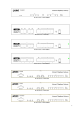
Front Panel of VIP-480FO Rear Panel of VIP-480 Rear Panel of VIP-480FS Rear Panel of VIP-480FO Front Panel of VIP-880 Front Panel of VIP-882 Front Panel of VIP-880FO 9
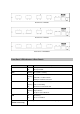
Rear Panel of VIP-880 Rear Panel of VIP-882 Rear Panel of VIP-880FO Front Panel LED Indicators & Rear Panels Front Panel LED PWR State Descriptions On GW is power ON Off GW is power Off CPU Flashing The system is running WAN Port ON GW network connection established Flashing Data traffic on cable network Off Waiting for network connection LAN Port ON LAN is connected successfully Flashing Data is transmitting FXS Off Ethernet not connected to PC ON Telephone Set is On-Hook Flashing R
NOTE: System initialization will turn some LEDs ON for a few seconds. Rear Panel Descriptions The WAN port supports auto negotiating Fast Ethernet 10/100Base-T WAN networks. This port allows your voice gateway to be connected to an Internet Access device, e.g. router, cable modem, ADSL modem, through a CAT.5 twisted pair Ethernet cable. LAN The LAN port supports 4 10/100Base-T switch hub networks.
Chapter 2 Preparations & Installation 2 Physical Installation Requirement This chapter illustrates basic installation of VIP-480/VIP-880 series • Network cables. Use standard 10/100BaseT network (UTP) cables with RJ45 connectors. • TCP/IP protocol must be installed on all PCs.
Note Please locate your PC in the same network segment (192.168.0.x) of VIP-480/880. If you’re not familiar with TCP/IP, please refer to related chapter on user’s manual CD or consult your network administrator for proper network configurations. LAN/WAN Interface quick configurations Nature of PLANET VIP-480/VIP-880 is an IP Sharing (NAT) device, it comes with two default IP addresses, and default LAN side IP address is “192.168.0.1”, default WAN side IP address is “172.16.0.1”.
Parameter Description LAN IP address of VIP-480/VIP-880 IP address Default: 192.168.0.1 Subnet Mask Hint LAN IP address of VIP-480/VIP-880 Default: 255.255.255.0 It is suggested to keep the DHCP server related parameters in default state to keep machine in best performance. After confirming the modification you’ve done, Please click on the Apply button to macke the changes effective, and click “Save Configuration” to save configuration.
Chapter 3 3 Network Service Configurations Configuring and monitoring your VoIP Gateway from web browser The VIP-480/VIP-880 integrates a web-based graphical user interface that can cover most configurations and machine status monitoring. Via standard, web browser, you can configure and check machine status from anywhere around the world. Overview on the web interface of VoIP Gateway With web graphical user interface, you may have: More comprehensive setting feels than traditional command line interface.
VIP-480/VIP-880 main page Wizard Setup for Quick Start Wizard Setup After finishing the authentication, the Main menu will display 3 parts of configuration, please click “Wizard Setup” to enter quick start: 1. WAN Port Type Setup (Setup First) For most users, Internet access is the primary application. The Gateway support the WAN interface for Internet access and remote access. The following sections will explain more details of WAN Port Internet access and broadband access setup.
ADSL Dial-Up User (PPPoE Enable) Some ISPs provide DSL-based service and use PPPoE to establish communication link with end-users. If you are connected to the Internet through a DSL line, check with your ISP to see if they use PPPoE. If they do, you need to select this item.
2. Configuring NAT or Bridge setting: Bridge Mode: When working on Bride Mode, the VoIP gateway will use only the LAN setting IP, The VoIP gateway will use the same LAN IP setting as WAN IP. That means, when Bride mode enable, the WAN connection setting will be ignored. NAT mode: LAN IP Network Configuration IP Address Subnet Mask Private IP address for connecting to a local private network (Default: 192.168.0.1) Netmask for the local private network (Default: 255.255.255.0) 3.
STEP2 : configure the numbering with phone/line ports. Phone Number The representation number is the phone number of the telephone that is connected to Phone port Line ports are connected to the extension ports of the PBX system or the PSTN line. They have a common Line Hunting Group Number. When this number is dialed, the Gateway system will find a free FXO line connected to Line Number PBX. This hunting will skip all busy lines and absent lines and find only the idle line to the PBX.
In the “Outgoing Dial Plan” settings: “Leading Number” is the leading digits of the dialing number. “Min Length” and “Max Length” is the min/max allowed length you can dial. “Strip Length” is the number of digits that will be stripped from beginning of the dialed number. “Prefix Number” is the digits that will be added to the beginning of the dialed number. “Destination” is the IP address of the destination Gateway that owns this phone number.
Chapter 4 System Configurations 4 Advance Setup of Network Setup In Advanced Setup, GW provides user two major parts function to configure: One is “Network Setup”, the other one is “VoIP Call Setup” Network Setup Label WAN Setting LAN Setting Sets/changes the WAN port Type like “Fixed IP”, “DHCP Client” or ”PPPoE”. Modifies the IP address of the LAN port and setting DHCP Server parameters.
the following setup page will be shown.Three methods are available for Internet Access. You are a leased line user with a fixed IP address; fill out Static IP the following items with the information provided by your ISP. IP Address check with your ISP provider Netmask check with your ISP provider Default Gateway check with your ISP provider PPPoE for ADSL Some ISPs provide DSL-based service and use PPPoE to establish communication link with end-users.
DHCP Client (Dynamic IP): (get WAN IP address automatically) IP Address: If you are connected to the Internet through a Cable modem line then a dynamic IP address will be assigned. Note WAN port display the IP address, Subnet Mask and Default gateway IP address if DHCP client is successful LAN Setting There are two kinds of network feature to configure: Bridge Mode and NAT Mode Bridge Mode: Select this Gateway as Bridge.
DHCP Server Configuration DHCP stands for Dynamic Host Configuration Protocol. It can automatically dispatch related IP settings to any local user configured as a DHCP client. The DHCP server supports up to 253 users (PCs) on Yes: Enables the DHCP server. No: Disables the DHCP server. Start IP Address Sets the start IP address of the IP address pool. End IP Address Sets the end of IP address in the IP address pool. DNS Server IP Address DNS stands for Domain Name System. Every Internet host.
Public Port Specifies which port should be redirected to the internal host. Private IP Specifies the private IP address of the internal host offering the service. Private Port Specifies the private port number of the service offered by the internal host. Apply Click here to add the port-mapping entry and enable the service. Dynamic DNS DDNS is a service that maps Internet domain names to IP addresses.
User Name Input your DDNS User Name Password Input your DDNS Password Domain Name Input you set from your DDNS DNS Server IP Input your DNS Server IP Netwrok Management Network Parameter allows you to modify the access port of gateway.
Advance Setup of VoIP Setup In Advanced Setup, GW provides user two major parts function to configure: One is “Network Setup”, the other one is “VoIP Call Setup” VoIP Setup Label The S Series Gateway support 4 / 8 phone/line for SIP and VoIP Basic H.323 VoIP call applications. You can configure these ports from this menu. Dialing Plan Users could apply any dial policy by setting Dial Plan including outgoing dial plan and incoming dial plan.
VoIP Basic Configuration to H.323 protocol VoIP Basic Configuration: (Configure the VoIP protocol to H.323 Protocol) Configure the numbering with FXS / FXO ports. (Depending on model) FXS Number: The representation number is the phone number of the telephone that is connected to FXS port. FXO Number: FXO ports are connected to the extension ports of the PBX system or the PSTN line. They have a common Line Hunting Group Number.
H.323 Parameters Label H.323 ID Sets the unique name of this Gateway, that is communicated as part of H.323 messaging. Primary Gatekeeper IP There are two gatekeeper address fields, one is primary, Address the other secondary. If this gateway does not want to register to any gatekeeper, just set value 0 to the primary gatekeeper address. If the primary gatekeeper address is Secondary Gatekeeper IP Address not 0, the gateway will register to the primary gatekeeper.
H.323 Call Pass through NAT H.323 ID Sets the unique name of this Gateway, that is communicated as part of H.323 messaging. 1. Disable : The Gateway operates in public IP address 2. Auto Detection: When the Gateway register to GNU H.323 Pass Through NAT method Gatekeeper, please select this option. 3. Manual Setting: When the Gateway registers to H.323 Gatekeeper and operate under NAT (enable DMZ), please select this option and key in IP address. Dialing Plan to H.
Example1: Normally Dial 001x leading call out, call to Destination IP address: 172.16.0.100 002x leading call out, call to Destination Domain Name: h323gw.test.com Example2: Speed Dial If user dial “101”, Gateway automatically dials “1234567890” to Destination IP address: 172.16.0.101 If user dial “202” Gateway automatically dials “0987654321” to Destination IP address: 172.16.0.
If Port 1 and 2 are busy, Port 3 will be ringing. If Port 1, Port 2 and Port 3 are busy, Port 4 will be ringing. Note: “123” will be register to H.323 Gatekeeper if “Register to GK” was enabled, show as below: Example2: Hunting for FXO Port Port 1: FXO was connected to PSTN. Port 2: FXO was connected to PSTN. Port 3: FXO was connected to PSTN. Port 4: FXO was connected to PSTN. H.323 number “123” call incoming, Port 1 will be off-hook and hear the Dial Tone from PSTN.
Example3: Termination Call to FXO for One-Shoot Call Port 1: FXO was connected to PSTN (area code is 81xxxxxxxx). H.323 leading number “081x”incoming, and delete the first one digit “0”, and call to PSTN number. Note: “081x” will be registered to H.323 Gatekeeper if “Register to GK” was enabled, show as below: Example4: Termination Call to FXO Port 1: FXS Port 1: FXO was connected to PSTN (area code is 92xxxxxxxx).
Advance Setting to H.323 protocol In Advanced Setting , GW provides user three major parts function to configure: One is “VoIP Advance”, the other one is “Telephone Advance” and “Network Advance” H.323 VoIP Advance Configurtion If this function is enabled, when VoIP call is occurred, the Smart-QoS other data will be automatically reduced traffic which across the internet in order to guarantee the voice bandwidth.
T.30/T.38 real-time FAX compliant Voice/FAX auto-switch. The T.38 is a “Real Time Group 3 Fax Communication over FAX Mode Option IP network” format. That’s meaning it’s a protocol for Fax over IP. You have to enable this function. This command configures the number of seconds that the gateway should be considered active by the H.323 H.323 RRQ TTL gatekeeper. The gateway transmits this value in the RRQ message to the gatekeeper.The default value is “0”. There are 2 choices for this setting.
Ring Frequency You can configure how long the Ring Frequency do you want to use. Enable battery reverse to detect polarity from PSTN line. FXO Battery Reverse The PSTN line can send H.323 case: Sending the Q.931 connect signal to caller when detecting polarity reverse from PSTN Line. When user calls the PSTN line which was connected with the FXO port, there are three answer mode for user to configure. 1. Ringing Answer Mode (Default Setting): FXO answer the call once the ring coming from PSTN line. 2.
3. Non Answer Mode: FXO will NOT answer the call in any time. (Note: Some ITSP only let the FXO for termination function, they do not user use the FXO port for origination) H.323 Call Connecting Answer Mode Case B: Hot Line Number” was assigned and the Hot line number belongs to remote H.323 device. (Note: The remote H.323 device need Disable the “Auto Answer”) 1. When the call com from PSTN to FXO, FXO start the Hot line dialing to remote H.323 gateway 2. The phone of remote H.323 gateway start ring. 3.
H.323 Netwrok Advance Configuration If this function is enabled, when VoIP call is occurred, the Smart-QoS other data will be automatically reduced traffic which across the internet in order to guarantee the voice bandwidth. Bandwidth control G.723/G.729 Bandwidth IP TOS You can configure your bandwidth what the Max byte of download and upload of ADSL modem rate. Enable / Disable Type of Service in IP packets.
SIP Hunting Table: This allows gateway can answer SIP call from internet by Hunting. For example: Port 1and Port 2 is hunting for the Port 1 SIP account. Then when port 1 are on call, the other one SIP call from internet will ring port 2. SIP Proxy Server Setting Enter the SIP service IP address or domain name in this SIP Proxy Server Setting field (the domain name that comes after the @ symbol i n a full SIP URI).
SIP NAT Traversal Method NAT Traversal Method: STUN Client / Symmetric RTP Dialing Plan to SIP protocol The “Dialing plan” needs setting when the user uses the method of Peer-to-Peer SIP VoIP call or registering SIP Proxy Server Mode. The SIP Dialing Plan has two kinds of directions: Outgoing (call out) and Incoming (call in).
Example1: Normally Dial 2290x leading call out, call to Destination Domain Name: sipgw.test.com 221 leading call out, call to Destination IP Address: 172.16.0.100 Example2: Speed Dial If user dial “101”, Gateway automatically dials “1234567890” to Destination IP address: 172.16.0.101 If user dial “202” Gateway automatically dials “0987654321” to Destination IP address: 172.16.0.
Example1: Hunting for FXS Port Port 1: FXS Port 2: FXS Port 3: FXS Port 4: FXS H.323 number “123”call incoming, Port 1 will be ringing. If Port 1 is busy, Port will be ringing. If Port 1 and 2 are busy, Port 3 will be ringing. If Port 1, Port 2 and Port 3 are busy, Port 4 will be ringing. (Note: “123” will be NOT register to SIP Proxy Server when Gateway is Registering SIP Proxy Server Mode) Example2: Hunting for FXO Port Port 1: FXO was connected to PSTN. Port 2: FXO was connected to PSTN.
(Note: “081x” will be NOT register to SIP Proxy Server when Gateway is Registering SIP Proxy Server Mode) Advance Setting to SIP protocol In Advanced Setting , GW provides user three major parts function to configure: One is “VoIP Advance”, the other one is “Telephone Advance” and “Network Advance” SIP VoIP Advance Configurtion After the VoIP call is connected, when you dial a digit, this digit is sent to the other side by DTMF tone. There are three methods of sending the DTMF tone.
SIP Telephone Advance Configuration If this function is enabled, when silence is occurred for a Silence Compression period of time, no data will be sent across the network during this period in order to save bandwidth. Disable / Enable dialing complete tone. Dial Complete Tone The Codec is used to compress the voice signal into data packets. Each Codec has different bandwidth requirement. Voice Codec option There are four kinds of Codec, G.723, G.729AB, G.711_u and G.711_A. The default value is G.723.
Ring Frequency You can configure how long the Ring Frequency do you want to use. Enable battery reverse to detect polarity from PSTN line. FXO Battery Reverse The PSTN line can send SIP case: Sending the 200 OK connect signal to caller when detecting polarity reverse from PSTN Line. When user calls the PSTN line which was connected with the FXO port, there are three answer mode for user to configure. 4. Ringing Answer Mode (Default Setting): FXO answer the call once the ring coming from PSTN line. 5.
4. Once FXO port receives the “SIP 200 OK” signal, FXO port would off-hook to answer the PSTN call. Case C: “Hot Line Number” was setting and the Hot line number was assigned to another FXS port in same Gateway. 1. When the call com from PSTN to FXO, FXO start the Hot line dialing to FXS port. 2. The phone start ring. 3. Once the phone was picked up, FXO port would off-hook to answer the PSTN call.
SIP Netwrok Advance Configuration If this function is enabled, when VoIP call is occurred, the Smart-QoS other data will be automatically reduced traffic which across the internet in order to guarantee the voice bandwidth. Bandwidth control G.723/G.729 Bandwidth IP TOS You can configure your bandwidth what the Max byte of download and upload of ADSL modem rate. Enable / Disable Type of Service in IP packets.
Chapter 5 System Administrations 5 Management Management Label You can save configuration and restart the gateway with Save Configuration the default configuration or with the current running configuration. Access Control Users can Sets/changes the administrator password... Set to Default You can restart the gateway with the default configuration. Backup/Restore User can backup the configuration file of Gateway to PC or Configuration Restore the configuration file from PC.
Access Control Changing the Administrator/Guest Password For security reasons, we strongly recommend that you set an administrator/password for the router. On first setup the router requires no password. If you don’t set a password the router is open and can be logged into and settings changed by any user from the local network or the Internet. Click Access Control Setup, the following screen will open.
Backup/Restore Configuration to a File User can backup the configuration to a File at Microsoft Operation System. And also restore the configuration file to the GW from PC. System Information Display Function Click System Information Display to open the Online Status page. In the example, on the foll owing page, both PPPoE connections is up on the WAN interface, H323/SIP Status, MAC addr ess, Register Status.., etc.
SNTP Setting Function Click SNTP setting to open the Online Status page. In the example, on the following page, . Use SNTP Setting— when checked, Gateway uses a Simple Network Time Protocol (SNTP) to set the date and time. The Gateway synchronizes the Gateway’s time after you select the time zone. Use SNTP Setting; Select the time zone which Gateway was at. Syslog setting Use Syslog server to record your Gateway log file. You can set you syslog server IP address for this function.
Capture packetackets Function Use “Capturer Packets” to record Gateway packets. You can start and stop the capture then save the file to PC. Use the Ethereal Tool (www.ethereal.com) to analyze the packets.
Appendix A FAQ Q: What is the default administrator password to login to the gateway? A: By default, your default username is “admin”, default password is “123” to login to the router. For security, you should modify the password to protect your gateway against hacker attacks. Q: I forgot the administrator password. What should I do? A: Press the Reset button on the rear panel for over 5 seconds to reset all settings to default values.
Appendix B Voice communications The chapter shows you the concept and command to help you configure your VoIP gateway through sample configuration. And provide several ways to make calls to desired destination in VIP-480/VIP-880. In this section, we’ll lead you step by step to establish your first voice communication via web browsers operations. Concepts: Voice Port There are two type of the voice port, FXO (Foreign exchange Office) and FXS.
FXS (Foreign exchange Station) port The FXS port allows the connection to an end node, like telephone, fax machine, or out-line of PBX system. FXS port is as like your local phone service provider who provides a number to you. It is easy to tell that after you have connected an end-device to FXS port and you will hear the dial-tone from FXS port once the hand set off-hook. FXS 222 412-1111 The FXS port is with voltage and current. DO NOT connects the port to any Caution PBX extension line or PSTN line.
H.323 VoIP Call: Peer-To-Peer Mode Scenario 1: H.323 VoIP Call: Peer-To-Peer Mode Gateway 1 to Gateway 2 PLAR connection H.
Scenario 2: H.323 VoIP Call: Peer-To-Peer Mode Gateway 1 (with PBX) to Gateway 2 PLAR connection H.
Scenario 3: H.323 VoIP Call: Peer-To-Peer Mode Gateway 1 (with PBX/PSTN) to Gateway 2 PLAR connection Call Method: Two-Stages-Dialing H.
Scenario 4: H.323 VoIP Call: Peer-To-Peer Mode Gateway 1 (with PBX/PSTN) to Gateway 2 PLAR connection Call Method: One-Shot-Dialing H.
Scenario 5: H.323 VoIP Call: Peer-To-Peer Mode Gateway 2 to Gateway 1 (Remote Call PSTN number) PLAR connection Call Method: One-Shot-Dialing H.
Scenario 6: H.323 VoIP Call: Peer-To-Peer Mode Gateway 2 to Gateway 1 (Remote Call PSTN number) PLAR connection Call Method: One-Shot-Dialing H.
Scenario 7: H.323 VoIP Call: Register to Gatekeeper Gateway 1 to Gateway 2 PLAR connection H.
Scenario 8: H.323 VoIP Call: Register to Gatekeeper Gateway 2 to Gateway 1 (Call PBX extension number) PLAR connection Call Method: Two-Stages-Dialing H.
Scenario 9: H.323 VoIP Call: Register to Gatekeeper Gateway 2 to Gateway 1 (Remote Call PSTN number with PBX) PLAR connection Call Method: Two-Stages-Dialing H.
Scenario 10: H.323 VoIP Call: Register to Gatekeeper Gateway 2 to Gateway 1 (Remote Call PSTN number with PBX) PLAR connection Call Method: One-Shot-Dialing H.
Scenario 11: H.323 VoIP Call: Register to Gatekeeper Gateway 2 to Gateway 1 (Remote Call PSTN number) PLAR connection Call Method: One-Shot-Dialing H.
Scenario 12: H.323 VoIP Call: Register to Gatekeeper Gateway 2 to Gateway 1 (Remote Call PSTN number) PLAR connection Call Method: One-Shot-Dialing H.
SIP VoIP Call: Peer-To-Peer Mode Scenario 13: SIP VoIP Call: Peer-To-Peer Mode Gateway 1 to Gateway 2 PLAR connection SIP Call (Peer-To-Peer Mode) Outgoing Dial plan Outgoing Dial plan No: 8x | Digit: 3~3, Des | GW1 IP address No: 9x | Digit: 3~3, Des | GW1 IP address x: wild card Des: Destination IP Digit: Digit Length min~ max WAN Gateway#1 Gateway#2 801 901 801 901 68
Scenario 14: SIP VoIP Call: Peer-To-Peer Mode Gateway 2 to Gateway 1 (Call PBX extension number) PLAR connection Call Method: Two-Stages-Dialing SIP Call (Peer-To-Peer Mode) with PBX: Call PBX Extension Method 1: Two-Stage-Dialing Outgoing Dial plan Outgoing Dial plan No: 8x | Digit: 3~3 |Des GW2 IP address No: 9x | Digit: 3~3 |Des: GW1 IP address No: 6x | Digit: 3~3 |Des: GW1 IP address x: wild card Des: Destination IP Gateway#1 WAN Gateway#2 Extension 609 801 901 801 Extension 601 609, 601 69
Scenario 15: SIP VoIP Call: Peer-To-Peer Mode Gateway 2 to Gateway 1 (Remote Call PSTN number with PBX) PLAR connection Call Method: Two-Stages-Dialing SIP Call (Peer-To-Peer Mode) with PBX: Remote Call PSTN number Method 1: Two-Stages-Dialing Outgoing Dial plan Outgoing Dial plan No: 8x | Digit: 3~3, Des | GW2 IP address No: 9x | Digit: 3~3, Des | GW1 IP address No: 6x | Digit: 3~3, Des | GW1 IP address x: wild card Gateway#1 Des: Destination IP WAN Gateway#2 Digit: Digit Length min~ max Extensi
Scenario 16: SIP VoIP Call: Peer-To-Peer Mode Gateway 2 to Gateway 1 (Remote Call PSTN number with PBX) PLAR connection Call Method: One-Shot-Dialing SIP Call (Peer-To-Peer Mode) with PBX: Remote Call PSTN number Method 2: One-Shot-Dialing Outgoing Dial plan Outgoing Dial plan No: 8x | Digit: 3~3, Des | GW2 IP address No: 9x | Digit: 3~3 | Des: GW1 IP address Incoming Dial Plan No: 6x | Digit: 3~3 | Des: GW1 IP address No: 02x | Digit: 3~10 |Strip:2 |Prefix: 0,,, | fxo port No: 02x| Digit: 3~10 | De
Scenario 17: SIP VoIP Call: Peer-To-Peer Mode Gateway 2 to Gateway 1 (Remote Call PSTN number) PLAR connection Call Method: One-Shot-Dialing SIP Call (Peer-To-Peer Mode) : Remote Call PSTN number Method: One-Shot-Dialing Outgoing Dial plan Outgoing Dial plan No: 8x | Digit: 3~3, Des | GW2 IP address No: 9x | Digit: 3~3 | Des: GW1 IP address Incoming Dial Plan No: 6x | Digit: 3~3 | Des: GW1 IP address No: 02x | Digit: 3~10 |Strip:2 |fxo port No: 02x| Digit: 3~10 | Des: GW 1 IP address Gateway#1 x:
Scenario 18: SIP VoIP Call: Peer-To-Peer Mode Gateway 2 to Gateway 1 (PSTN Call PSTN number) PLAR connection Call Method: One-Shot-Dialing SIP Call (Peer-To-Peer Mode) : PSTN Call PSTN number Method: One-Shot-Dialing Outgoing Dial plan Outgoing Dial plan No: 8x | Digit: 3~3, Des | GW2 IP address No: 9x | Digit: 3~3 | Des: GW1 IP address No: 04x| Digit: 3~10 | Des: GW2 IP address No: 6x | Digit: 3~3 | Des: GW1 IP address Incoming Dial Plan No: 02x| Digit: 3~10 | Des: GW 1 IP No: 02x | Digit:3~10 |
Scenario 19: SIP VoIP Call: Register to SIP Proxy Server Gateway 1 to Gateway 2 PLAR connection SIP Call (Register to SIP Proxy Server Mode) Register Number List GW1: 801 GW2: 901 SIP Proxy Server WAN Gateway#2 Gateway#1 901 801 801 901 74
Scenario 20: SIP VoIP Call: Register to SIP Proxy Server Gateway 2 to Gateway 1 (Call PBX extension number) PLAR connection Call Method: Two-Stages-Dialing SIP Call (SIP Proxy Server Mode) with PBX: Call PBX Extension Method 1: Two-Stage-Dialing Register Number List GW1: 801 GW2: 901,609 SIP Proxy Server Gateway#1 WAN Gateway#2 Extension 609 801 901 801 Extension 601 609, 601 75
Scenario 21: SIP VoIP Call: Register to SIP Proxy Server Gateway 2 to Gateway 1 (Remote Call PSTN number with PBX) PLAR connection Call Method: Two-Stages-Dialing SIP Call (SIP Proxy Server Mode) with PBX: Remote Call PSTN number Method: Two-Stages-Dialing Register Number List GW1: 801 GW2: 901,609 SIP Proxy Server Gateway#1 WAN Gateway#2 Extension 609 02-12345678 Trunk-Line 801 901 801 PSTN Extension 601 609, 0, 12345678 76
Scenario 22: SIP VoIP Call: Register to SIP Proxy Server Gateway 2 to Gateway 1 (Remote Call PSTN number) PLAR connection Call Method: Two-Stages-Dialing SIP Call (SIP Proxy Server Mode) : Remote Call PSTN number Method: Two-Stages-Dialing Register Number List GW1: 801 GW2: 901,904 SIP Proxy Server Gateway#1 WAN Gateway#2 904 FXO 02-12345678 801 901 801 PSTN 904, 12345678 77
Scenario 23: SIP VoIP Call: Register to SIP Proxy Server Gateway 2 to Gateway 1 (PSTN Call PSTN number) PLAR connection Call Method: Two-Stages-Dialing SIP Call (SIP Proxy Server Mode) : PSTN Call PSTN number Method: Two-Stages-Dialing Register Number List GW1: 801,804 GW2: 901,904 SIP Proxy Server Gateway#1 Gateway#2 904 804 FXO FXO 02-87654321 02-12345678 WAN 901 04-56785678 801 87654321, 804, PSTN PSTN 56785678,904, 12345678 04-43221344 78
Appendix C VIP-480 series Specifications Product Model Hardware WAN LAN Voice Protocols and Standard Standard Voice codec Fax support Voice Standard Protocols Advanced Function 4-Port H.323/SIP VoIP Gateway VIP-480 VIP-480FS VIP-480FO 1 x 10/100Mbps RJ-45 port 4 x 10/100Mbps RJ-45 port 4 x RJ-11 connection 4 x RJ-11 connection ( 2 x FXS, 2 x FXO) ( 4 x FXS) 4 x RJ-11 connection ( 4 x FXO) H.
VIP-880 series Specifications Product Model Hardware WAN LAN Voice Protocols and Standard Standard Voice codec Fax support Voice Standard Protocols Advanced Function Network and Configuration Access Mode Management LED Indications Dimension (W x D x H) Operating Environment Power Requirement EMC/EMI 8-Port H.