-port H.
CONTENTS Chapter 1 VIP-2100 Introduction ................................................................. 1 SYSTEM DESCRIPTION .................................................................................... 1 TECHNICAL SPECIFICATION.............................................................................. 2 AUDIO FEATURE ............................................................................................. 2 VIP-2100 DETAIL SPECIFICATIONS ....................................................
DIGIT MANIPULATION .................................................................................... 50 CALL FLOW EDITOR ...................................................................................... 50 CONFIGURATION MANAGER ........................................................................... 50 APPLY CHANGE ............................................................................................ 51 Chapter 7 Advance Configuration Reference ..........................................
Appendix 4 Interface LED Description .................................................. 116 Appendix 5 Build-in Voice Prompt Index................................................ 117 Appendix 6 Timezone to Country Mapping List...................................... 118 Appendix 7 IP Bandwidth Requirement................................................... 120 Appendix 8 Release Complete Cause Code............................................ 121 Appendix 9 RADIUS Format Attributes..............................
VIP-2100 User’s manual -4-
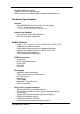
Chapter 1 VIP-2100 Introduction System Description VIP-2100 is a cost effective solution for VoIP trunk gateway supporting one-, port T1/E1 VoIP trunks that provides voice and fax over IP network. It supports ITU-T H.323 V3, SIP RFC 2543/3261, SNMP V2, Call Detail Record, WEB management and other useful functions to meet customer requirements. The built-in enhanced IVR (Interactive Voice Response) and Billing Service of VIP-2100 is suitable for prepaid and postpaid service.
- Multiple configuration saving Provides CDR (Call Detail Record) Built-in internal user authentication for prepaid & postpaid users Technical Specification Interface - Two 10/100MB Ethernet Ports (Host & VoIP stream) - 1 xT1/E1 (120 Ohm-RJ48C connectors) 75 Ohm needs external 3rd party BNC/RJ-48C adapter cables Protocol and Standard - ITUT H.323 v3 and H.450 compliance - SIP RFC 2543/3261 compliance Audio Feature - Codec -- G.711 A/μ-Law, G.723.1 (5.3K/6.3K), G.729A, G.729 Support G.
- Selected disconnect cause code & behavior Management Feature - OS and program upgradeable - Console port: RS-232 port - TELNET - Full Web management interface & real time monitor - Front panel LCD - SNMP v2 (H.
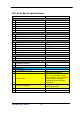
VIP-2100 Detail Specifications Feature VIP-2100 Physical Dimension 1 Width 2 Height 3 Depth 4 Industrial rack mount 5 Color 6 Weight Power / Environmental 1 Power 2 Operating temperature 3 Relative humidity Processors & Storage 1 DSP vendor 2 Operation System 3 RAM 4 Program/Data Storage 5 OS Upgradeable 7 Program Upgradeable Front Panel Display 1 LED status 2 LCD status LAN Interface 483mm 44mm 450mm Yes Black 8Kg 90-240V auto switch 0~60 C 5%~95% Intel Pentium, AudioCodes DSP XP Embedded 512 MB 256 MB
T1 CAS DTMF/R1MF 7 T1 ISDN PRI Support 8 9 Trunk Spans 10 Default Trunk Channel Mask 11 PSTN Line Hunting 12 PSTN Line Hunting Channel Selection 13 On the Fly Reset Channel/Trunk Audio Codec Support 1 G.711 A-law 2 G.711 u-law 3 G.723.1 4 G.729A 5 Selectable Payload Size - G.711 6 Selectable Payload Size - G.723 7 Selectable Payload Size - G.729 Fax Transmission 1 Bypass mode 2 CISCO Compatible 3 ECM Support 4 FAX auto-detection 5 H.323 Annex D Support 6 SIP- T.38 Reinvite 7 T.38 During fast connect 8 T.
3 G.
SIP Protocol Support 1 Cause Code Mapping 2 HTTP Digest Authentication 3 SIP Call on Hold 4 SIP Early Media 5 SIP Overload Redirect 6 SIP Transfer (unattend) 7 SIP Transfer (attend) 8 SIP/TCP 9 SIP/UDP 10 SIP-180/SDP 11 SIP-183/SDP 12 SIP-PRACK 13 SIP-RFC 3261 14 SIP-RFC 3264 (Offer/Answer) H.
7 H.323 to SIP FAX Relay 7 PSTN to H.323 Call 8 PSTN to PSTN Call 9 PSTN to SIP Call 10 SIP to H.
6 VoIP Prepaid Support Embedded AAA 1 Embedded Prepaid Service 2 Embedded Postpaid Service 3 Point/second Calculation 4 Second/point calculation 5 Auto Disable/Clean User 6 PSTN Prepaid Support 7 VoIP Prepaid Support System Limitation 1 Max DM 2 Max IP ACL 3 Max DNIS ACL 4 Max ANI ACL 5 Max User ACL 6 Max Phone Book Entries 7 Max Call Flow Component 8 Max CDR Keep Days 9 Max Voice File Storage Manual 1 English User Guide VIP-2100 User’s manual Yes Yes Yes Yes Yes Yes Yes Yes 4096 2048 4096 4096 20000 1000
VIP-2100 Appearance Description VIP-2100 Front Panel: 2 7 5 1 3 4 8 6 Functions: 1: Power LED 2: Network1 Interface LED 3: Network2 Interface LED (not used) 4: H/D LCD 5: Power Switch 6: System Status LED 7: LCD Panel 8: LCD Touch Panel VIP-2100 Rear Panel: 3 1 2 7 5 4 Functions: 1: Electric Fan 2: AC Power outlet 3: AC Power switch (Keep on) 4: Trunk E1/T1 port 5: VoIP Ethernet port 6: Keyboard/Mouse 7: Com1 port 8: Ethernet port 9: VGA 10: print port (not available) VIP-2100 User’s manual
Chapter 2 Logon VIP-2100 After connected E1/T1 & Ethernet cables into the VIP-2100, turned on the power. The first step is to logon the system and set up the IP address. Before you can use the Browser to setup VIP-2100, you need to have Java Standard Runtime (1_4_1_02) to make it work. Please refer to Appendix 2 Java plug-in Install for detail. Logon VIP-2100 Setp1: Start IE5.0 (or later version) to navigate VIP-2100 Management System by typing the default IP address (the default URL is http://192.168.111.
Step 3: The screen shows the Home Page of VIP-2100 as figure 2.1-3. Figure 2.1-3 Network Configuration Step 1: After successfully logon to the system, we need to change the network configuration. Click Control→Network to setup the network parameters as figure 2.2-1. Figure 2.
Step 2: Enter the deserved IP address, Submask and default gateway. Apply the change by clicking apply button as figure 2.2-2. Figure 2.2-2 Step 3: When screen shows “Setup network configuration successfully!” It means the IP Network setting is successfully changed as figure 2.23. Figure 2.2-3 ☻Note: “Network Control” takes around 5-second to apply the new network configuration. Please logon again with new IP address after 5 seconds.
Figure 2.3-2 Step 3: Enter current date and time. Apply the change by clicking Apply button as figure 2.3-3. Figure 2.3-3 Step 4: The screen will shows “Setup system time successfully!” It means the System Time setting is successfully changed as figure 2.3-4. Figure 2.3-4 Step 5: If you would like to use SNTP to sync time with a SNTP V4 Server, click Time Sync button to setup it as figure 2.3-5. Figure 2.3-5 Account Manager Step 1: You can manage your user account by click Control→Account Manager.
Figure 2.4-2 Field Description: • User ID: Login User ID • Password: Login Password • Confirm Password: Confirm new password again Step 3: When screen shows “Create user account successfully!” It means user account setting is successfully created as figure 2.4-3 Figure 2.
Relogin Step 1: Click Control→Relogin to relogon by another user account as figure 2.5-1. Figure 2.5-1 Step 2: Enter new User ID and Password to relogon the VIP-2100 as figure 2.5-2. Figure 2.5-2 Step 3: The screen shows the Home Page of VIP-2100 as figure 2-5-3. Figure 2.
Chapter 3 H.323 Gatekeeper and SIP Proxy Mode Configuration Environment used in this chapter H.323 GK and SIP Proxy Mode SIP Phone Gatekeeper H323 VoIP Network SIP VoIP Network H.323 Gateway Phone 1001 H323 Phone Proxy Server SIP USB Phone 8888 Process: PSTN → H.323 Call: DNIS (1001) → Make H.323 - Gatekeeper Call (1001) → SIP Call: DNIS (8888) → Make SIP – SIP Proxy Call (8888) H.323 → DNIS (5932111222) → DM (H.
Interface Configuration This section is going to setup the VoIP interface. Step 1: Now we are going to setup the VoIP interface, click Configuration→ Interface to setup VoIP T1/E1 interface as figure 3.1-1. Figure 3.1-1 Step 2: Double-click the installed interface (i.e Interface ID:0) to config it as figure 3.1-2. Figure 3.1-2 Step 3: Modify the VoIP Interface parameters (i.e. IP Address, Protocol Tag, Subnet Mask and Default gateway) and apply the change by clicking Apply as figure 3.1-3. Figure 3.
Frequency changed parameters: (Refer to section “Interface Configuration” for more detail) • IP Address: 192.168.19.174 • Subnet Mask: 255.255.255.0 • Default Gateway: 192.168.19.254 • PCM Type: A-law or Mulaw ☻Caution: Subnet Mask does not support Supernet. Step 4: After successfully to change the Interface configuration, the screen come back the page of Interface Configuration as figure 3.1-4. Figure 3.1-4 T1/E1 Trunk Configuration This section is going to setup the PSTN trunk parameters.
Step 2: Select the trunk to be modified, and click Modify button as figure 3.22. Figure 3.2-2 Step 3: Modify the trunk parameters (i.e. Trunk Type, Termin Side, Trunk Mode, Protocol Tag, Line Code) and apply the change by clicking Apply as figure 3.2-3. Figure 3.
Step 4: After modifications are made to the Trunk Configuration, the screen comes back the page of Trunk Configuration as figure 3.2-4. Figure 3.2-4 H.323 Configuration This section is going setup the H.323 parameter. If you only need SIP calls, you can skip it. Step 1: Click Configuration→H.323 to setup the H.323 parameters for Gatekeeper related information as figure 3.3-1. Figure 3.3-1 Frequency used parameters: • Register to Gatekeeper: Yes • Gatekeeper IP: 192.168.5.1 • E.164 Tel: 113 • Register H.
Step 3: You can see the screen display the new configuration of the H.323 Configuration as figure 3.3-3. Figure 3.3-3 SIP Configuration This section is going setup the SIP parameter. If you only need H.323 calls, you can skip it. Step 1: Click Configuration→SIP to setup the SIP parameters for SIP Proxy Server related information as figure.3.4-1. Figure 3.4-1 Frequency used parameters: • SIP Register: Yes • Primary Registar Server: 192.168.19.
• • • • Primary Outbound Proxy Server: 192.168.19.150 Primary Outbound Proxy Port: 5060 Primary Outbound Proxy User: 173 Primary Outbound Password: 173 Step 3: You can see the screen display the new configuration of the SIP Configuration as figure 3.4-2. Figure 3.4-2 Digit Manipulation The purpose of “Digit Manipulation” is to add or drop dialed digits for PSTN or IP side (Interface configuration for PSTN side & H.
Step 2: Enter the related parameters and click Apply button as figure 3.5-2. Figure 3.5-2 Field Description: • Group ID: 0 (DM Group identify) • Description: H.323: H323 In Drop SIP: SIP In Drop Step 3: Click the New created DM and Detail button to add digits setting as figure 3.5-3. Figure 3.5-3 Step 4: Click New button to add a new DM rule as figure 3.5-4. Figure 3.
Step 5: Create a new H.323 DM Group “1” and DM detail is show as follows: Figure 3.5-5 H.323 Incoming Call DM Setting: • Matched Pattern: 5 (pattern to be matched) • Group ID: 1-H323 In Drop (belong to this DM group) • Drop: 5 (drop digits) H.323 incoming call ↓ Dialed number: 582265699 ↓ Match the pattern 5 ↓ Delete 5 (Drop) ↓ New dialed number becomes 82265699 Step 5: Also create a new SIP DM Group ‘2” and DM detail is show as follows: Figure 3.
• Drop: 113 (drop digits) SIP incoming call ↓ Dialed number: 11307688222 ↓ Match the pattern 11307 ↓ Delete 113 (Drop) ↓ New dialed number becomes 07688222 Step 6: Create a PSTN incoming call DM Group “3” and DM detail is show as follows: Figure 3.
Outbound/Inbound DM Group) or Call Flow (refer to section “Call Flow Editor”) to take effect. Chapter 4 Call Flow Editor Call Flow Editor is used to control the call behavior including voice prompt, AAA, DM…etc. It requires Java run time to run.
Step 2: Drag and prop the required component icon into the workspace as figure 4-2.
o Failed Reason: Return code from RADIUS server o Line Propriety: - Invalid Account - Account In Use - Zero Balance - Account Expired - Over Credit Limit - Number of Retries Exceeded - Insufficient Balance J Note: Detail response attributes, please refer RADIUS Format Attributes • Answer: Answer incoming call (PSTN only) • Branch: Play an announcement and branch into different route o o o o o o • Voice File: Voice prompt file (“.
o o o o o • Check Parameter: Check parameter type (DNIS, ANI….) Digit From: Start digit from Digit To: End digit to Valid To: If the checked variable is success to validate Invaried To: If the checked variable is not success to validate CIB: Call Information Branch o Info Type: Information type selection - ANI: Calling Number - DNIS: Called Number - IP: IP Address or network (e.g. 192.168.0.
-DNIS: Called number -ANI: Calling number -IP: In coming IP address -User: User ID o Allow To: If it is met the ACL defined o Disallow To: If it is not met the ACL defined • CTB: Call Type Branch o PSTN To: Route for PSTN call o H.323 To: Route for H.
o DM Parameter: Manipulation ANI or DNIS o DM Group ID: Apply to DM group • MakeCall: Make Call to PSTN or H.323/SIP site o Route Mode: Gatekeeper Call or P2P Call or PSTN…etc. (for PSTN incoming call, please select the Gatekeeper, P2P Call, or SIP Proxy call TA; for H.323/SIP incoming call, please select the PSTN call) o Transport Address: When used for “H.323 TA” routing mode, the format used is “Ipaddr:port” (e.g. 192.168.111.
o Line Propriety: -PSTN: PSTN disconnect reason code: -Normal Call Clear -User Busy -No User Response -No Answer -Call Reject - VoIP: VoIP disconnect reason code: -User Busy -No Answer -Unreachable -Other • PA: Play Announcement o Dynamic Play: Dynamic play voice file by combine prefix and variable as the file name o Enable: Combine prefix to variable as the voice file to play -Prefix: Voice file prefix (e.g. prefix: WT, variable: user1 (contact 201, played voice file is “WT201.
• PCUI: Prompt and Connect User Information o o o o o o • Play Type: Dial tone or voice prompt selection Voice File: Voice prompt file Max DTMF: Maxtor of DTMF to be received. Assign To: Result (received DTMF) will be assign to End of DTMF: The digit to indicate dial end.
• Set Data: Assign value to a variable o Assign To: Assigned variable o Use SysParam: Use system parameter to replace or not o Value: ANI, DNIS, User ID or other digits • Start: Call flow start o Next Component • Quit: Disconnect calls VIP-2100 User’s manual - 35 -
Example Call Flow as figure 4-3. Example Description: Components Start Component ID: 1000 CTB Component ID: 1001 CIB Component ID: 1011 Contents Next Component: 1001 PSTN To: 1011 H.323 To: 1009 SIP To: 1008 Info Type: ANI Prefix: 1 goto: 1010 (H.
Next Component: 1006 Disc Component ID: 1005 Quit Component: 1006 1001 Route for H.323Gatekeeper call DM Parameter: DNIS DM Group ID: H.
Example Used Call Flow: VIP-2100 User’s manual - 38 -
Start:1000 CTB:1001 PSTN to:1011 H323 to: 1009 SIP to: 1008 to 1009 H.323 in 1011 PSTN in to 1008 SIP in DM: 1009 Call to PSTN CIB: 1011 Info Type: DNIS Prefix: 1 goto: 1010 Prefix: 8 goto: 1004 DM: 1008 Call to PSTN 8 1 Make Call: 1010 Make Gatekeeper Make Call: 1007 Call to PSTN Make Call: 1004 Make SIP call to H.
Load a Configuration: Step 1: When you need to load a saved configuration, click a saved configuration (i.e. 04/26/2004 Loading Test) item to load it back as figure 4.1-1. Figure 3.7-1 Step 2: When screen shows “Current configuration will lost! Are you sure to load this configuration?” click on OK button to load he saved configuration to the working configuration as figure 4.1-1. Figure 3.8-2 JNote: It is need to restart the system to take effect of the new-loaded working configuration.
Figure 3.8-4 Backup the working configurations: Step 5: To backup the running configuration, click on Backup button, to back up local hard disk. The whole running configuration will be compress into a zip file (file name: export.zip) and transfer back to local as figure 4.2-2. Figure 3.8-5 Restore configuration: Step 6: To restore the backup configuration file, click on Restore button, when screen shows “Import Configuration file”, select backup file (i.e. c:\export.
Apply Change When you load a new working configuration, the system must be restarted to take effect. Step 1: Click Configuration→Apply Change, the screen show “ The change you mode need to restart the system for apply please confirm to restart or do it later.” Click on OK/Cancel to restart the system or not as figure 4.3-1. Figure 4.
Chapter 5 Peer to Peer Mode Configuration Environment used in this chapter Peer to Peer SIP Phone H323 VoIP Network SIP VoIP Network H.323 Gateway Phone 1001 H323 Phone SIP USB Phone 8888 Process: PSTN → H.323 Call: DNIS (822656991001) → DM (PSTN In Drop) →Make H.323 - Peer to Peer Call (1001) → SIP Call: DNIS (822656998888) → DM (PSTN In Drop) →Make SIP - Peer to Peer Call (8888) H.323 → DNIS (50932123321) → DM (H.
H.323 Configuration Step 1: Change Register To Gatekeeper to “No” to enable peer to peer mode as figure 5.1-1. Figure 5.1-1 Frequency used parameters: • Register to Gatekeeper: No SIP Configuration Step 1: Change SIP Register to “No” to enable peer to peer mode as figure 5.2-1. Figure 5.
Address Book For making a Peer-to-Peer call, the IP device must has an address record in the phone book for routing. Step 1: Click Address Book adds a new address book for the peer to peer calls, New to add as figure 5.3-1. Figure 5.3-1 Step 2: Enter the related parameters and click Apply button as figure 5.3-2. Figure 5.3-2 Field Description: • Name: H.323 IP Phone or SIP-Cisco • Tel/Prefix: 1002 • Trans Address: - H.323 Call: 192.168.5.102 or 192.168.5.102:1720 - SIP Call: sip:8001@192.168.5.
Step 3: You can see the screen displays the new Address Book as figure 5.33. Figure 5.3-3 ☻Note: You must apply the change to take effect for the change.
Call Flow (P2P Mode): Start:1000 CTB:1001 PSTN to:1011 H323 to: 1009 SIP to: 1008 to 1009 H.
Apply Change Please refer to section “Apply Change” VIP-2100 User’s manual - 48 -
Chapter 6 SIP to H.323 Mode Configuration Environment used in this chapter SIP to H.323 SIP Phone H323 VoIP Network SIP VoIP Network H.323 Gateway H323 Phone SIP USB Phone 8888 Process: SIP → H.323 Call: DNIS (8861001) → DM (SIP In Drop) →Make H.323 (1001) H.323 → SIP (8868888) → DM (H.
Address Book Please refer to section “Address Book” Digit Manipulation Please refer to section “Digit Manipulation” Call Flow Editor Please refer to section “Call Flow Editor” Call Flow (P2P Mode): Start:1000 CTB:1001 PSTN:1010 H323: 1009 SIP: 1008 1009 H.323 in 1010 PSTN in 1008 SIP in Make Call: 1002 Make Peer to Peer Call to SIP / H323 Make Call: 1010 Make Gatekeeper call to H.
Apply Change Please refer to section “Apply Change” VIP-2100 User’s manual - 51 -
Chapter 7 Advance Configuration Reference Configuration System Configuration Start Path: Configuration→System Figure 7.1-1 Parameter Description: • CDR Mode: Call detail record generating mode (Refer to “Appendix 3 Retrieve CDR Information” for detail file description) o File Only: Log CDR into the file only. It can be retrieved by ftp (directory c:\cd cdr). o Radius Start/Stop: Log CDR into the file and send RADIUS start/stop billing message out. - VoIP: enable VoIP site RADIUS billing message or not.
• • • • • • Time Expired Notify: Seconds to be notifying caller before communication expired. This function is used for Pre-Paid calling card service and must cooperate with RADIUS Server. Almost Expired Tone: Communication expired notice tone selection Fast Response Timeout: The maximum times to wait for response. It’s depended on the network speed.
Advance Interface Configuration: Start Path: Configuration→Interface →Advance Figure 7.
• • • voice quality. Set to 12 will have long voice delay but with better voice quality EC Tail Length: Echo Cancellation Length, default value is 25ms Silence Compress: Enable silence compress or not TDM Bus Clock: TDM Bus clock source o Internal: derived from internal oscillator o External: derived from external PSTN E1/T1 clock Dial Plan Configuration Dial Plan can be used to assign the ISDN number plan based on prefix setting. Start Path: Configuration→Interface→Dial Plan Figure 7.
Figure 7.3-1 Basic Parameter Description: • Interface ID: System parameter • Trunk ID: System parameter • Trunk Type: T1or E1 selection • Description: Description for this trunk ID • Termin Side: Network site or User Site (normally, you set to “user site” when connect to switch) o User Side o Network Side • Trunk Mode: Trunk operation mode o Disable: Disable the trunk o Normal: Accept PSTN and VoIP calls o PSTN incoming only: Allow the PSTN incoming calls only o H.323 incoming only: Allow the H.
- T1 DMS100 ISDN - T1 NTT ISDN: used to connect NTT INS-1500 ISDN standard (Japan Only) - T1 HKT ISDN - T1 QSIG - T1 EURO ISDN - T1 DMS100 MERIDIAL ISDN - T1 NI1 ISDN o For E1: - E1 EURO ISDN: used for most of European ISDN standard - E1 MFCR2 - E1 CAS - E1 RAW CAS - E1 AUSTEL ISDN: Australia E1 ISDN Variance - E1 HKT ISDN: Hong E1 ISDN Kong Variance - E1 KOR ISDN: Korea E1 ISDN Variance - QSIO - E1 TNZ ISDN • Line Code: T1: you can choose AMI, B8ZS; E1: you can choose AMI, HDB3 • PSTN Trace: PSTN layer deb
Figure 7.3-2 Advance Parameter Description: • Interface ID: System parameter • Trunk ID: System parameter • Src Num Plan: ISDN source number plan • Dest Num Plan: ISDN destination number plan • Src Num Type: ISDN source number type • Dest Num Type: ISDN destination number type • Src Num Presen: ISDN source number presentation • Src Num Screen: ISDN source number display • Input Gain: Voice Gain from IP to PSTN side (default: 0 db) • Output Gain: Voice Gain from PSTN to IP side (default: 0 db) • Q.
Rest Configuration Reset a channel or a trunk idle state. Start Path: Configuration→Interface→Detail→Reset Figure 7.4-1 Start Path: Configuration→Interface→Detail→Reset Figure 7.4-2 Basic Parameter Description: • Trunk: Reset trunk ID • Channel: Rest channel selection - All Channel: Reset all channel - 0~31: Reset 0~30 logical channel to reset H.323 Configuration Start Path: Configuration→H.
Figure 7.5-1 Basic Parameter Description: • Register To Gatekeeper: Register to Gatekeeper or not o Yes: Register to GK o No: Not register to GK • Gatekeeper IP: Gatekeeper IP Address • Gatekeeper RAS: UDP Port number listened on Gatekeeper (default: 1719) • E.164 Tel: Telephone number to be registered to Gatekeeper • Register H.323 ID: H.
• • • • • o Disable: Don’t use Fast Start. o Enable Fast Start Both Site: Use Fast Start for incoming call and outgoing H.323 calls o Fast Start-H.323 incoming only: Enable Fast Start for H.323 incoming calls only o Fast Start-H.323 outgoing only: Enable Fast Start for H.323 outgoing calls only. o Early H.245: Use Early H.245 H.245 Tunneling: Transfer the H.245 message over the Q.931 channel H.450 Service: Enable the H.
• G.711 Psize: G.711 transmission packet size in ms (default: 20ms) SIP Configuration Start Path: Configuration→SIP Figure 7.
• • • • • • • • • • • • • • • • • • Primary Outbound Proxy Server: The IP address of an outbound Proxy the SIP Stack uses. Primary Outbound Proxy Port: The port of an outbound Proxy the SIP Stack uses Primary Outbound Proxy User: The User ID of an outbound Proxy the SIP Stack uses. Primary Outbound Proxy Password: The password of an outbound Proxy the SIP Stack uses. Secondary Outbound Proxy Server: The IP address of an outbound Proxy the SIP Stack uses.
Figure 7.6-2 Advance Parameter Description: • TCP Enable: Receive SIP TCP call or not. • Max TCP Connection: Max Call: The maximum SIP TCP calls. • Outbound Use TCP: Use SIP TCP for outbound call or not. If it set to no, UDP is used. • Register Use TCP: Use SIP/TCP to register to SIP register. • TCP Port: The local TCP port on which the SIP Stack listens. • UDP Port: The local UDP port on which the SIP Stack listens.
• • • • • • • • • • • • • • Application Pool Page Size: The size of page in the application pool Retransmission T1: T1 determines several timer as defined in RFC3261. For example, When an unreliable transport protocol is used, a Client Invite transaction retransmits requests at an interval that start at T1 seconds and doubles after every retransmission. A Client General transaction retransmits requests at an interval that starts at T1 and doubles until it reaches T2.
• • • • • • • • • • • Public Signal Port: The static mapped Port for RTP stream Public RTP IP: The static mapped RTP IP Public RTP Port: The static mapped RTP starting port Public RTP Port Interval: The VIP-2100 has at least 30 RTP channels. Each channel needs 3 ports mapping on NAT Server. The interval is used to caculate the right port for each channel.
Behind NAT Example 1: VIP-2100 NAT Server Setting One-by-One Static 192.168.111.112 210.59.163.11 IP Mapping Static Port Mapping 192.168.111.111:5060 210.59.163.10:10000 VIP-2100 NAT Enable Setting: Public Signal IP: 210.59.163.10 Public Signal Port: 10000 Public RTP IP: 210.59.163.11 Public RTP base port: 4000 (same as “Interface→Advance’s Config”) Public RTP Port Interval: 10 Behind NAT Example 2: Static Port Mapping RTP Channel 01 RTP Channel 02 VIP-2100 192.168.111.111:5060 192.168.111.
Access Control Access Control list can be used to filter the calls forms the IP Network, DNIS, and ANI. It must be used in call flow edit to take effect. IP ACL Start Path: Configuration→Access Control→IP ACL Figure 7.7-1 Parameters: • IP Network: IP Address or prefix used to be filtered • Access Mode: o Allow: the inputs IP Network are allowed for calls. o Disallow: The inputs IP Network are disallowed for calls.
DNIS ACL Start Path: Configuration→Access Control→DNIS ACL Figure 7.7-3 Parameters: • DNIS: Called party number used for filter • Access Mode: o Allow: The called numbers are allowed for calls o Disallow: The called numbers are disallowed for calls ☻Note: If in the system has both allowance and disallowance setup, the system will check allowance first and disallowance later. If only disallowance inputted all DNIS will allow to work except disallowed DNIS.
New a Calling Rate: The calling rate will have different appearance for different calling rate policy set in Radiu configuration. Click Calling Rate button to add a new calling rate as figure 7.7-5. Figure 7.7-5 Point per Second calling rate: Calling rate (point per second) is used to convert prepaid point into prepaid time in second. For example, you can set calling rate to 5 for “100” prefix. When a caller, which has 200 prepaid point, calls “100xxxx”, the max talk time will be 200/5=40 seconds.
Figure 7.7-7 Number Replace The purpose of “Number Replace” is to replace called number or calling number for PSTN or IP. It must be used in call flow to take effect. Step 1: It is useful for real PSTN number to virtual VoIP number replacement. Click Number Replace to add a new Number Replace Group, add as figure 7.8-1. Figure 7.8-1 Field Description: • Group ID: 1 (Number Replace Group identify) • Description: SIP in Step 2: Click the New created NR and Detail button to add digits setting as figure 7.
Figure 7.9-1 Parameters: • Group ID: Hunting Group ID • Description: Description of Hunting Group • Hunting Method: Route selection o Random: Random select a trunk within this hunting group o Priority: Select a trunk by priority. (Priority 1 has lowest priority; 9 has highest priority) o Round Robin: Call is hunting rotationally Start Path: Configuration→Routing Plan→Hunting Group→Detail Figure 7.
Call Routing The call routing can be used for hunting a PSTN trunk by prefix. Start Path: Configuration→Routing Plan→Call Routing Figure 7.9-3 Parameters: • Group ID: Select the T1/E1 according to the selection of Hunting Group ID when dialed number is matched • Number To Route: The dialed telephone number to be matched • Matched ANI Prefix: Calling party number used to filter • Allow Use Others: To select other T1/E1 trunk when all trunk are busy at your desired Hunting Group.
Figure 7.
• • o Disable: Don’t auto clean inactive user o Prepaid User: Auto clean prepaid user only o Postpaid User: Auto clean postpaid user only o All User: Auto clean inactive user Clean Filter: Auto clean filter o None: Auto clean users exceed clean period without access the network o Inactive: Auto clean only to inactive users Clean Period: The maximum unaccess days to clean up. When the clean filter is set Inactive, the unaccess day is start counting when the user is inacived Apply Change 1.
Chapter 8 System Control System Start path: Click Control→System Figure 8.1-1 Parameter: • Soft Reset: Soft Reset at VIP-2100 • Restart: Restart the VIP-2100 • Shutdown: Shutdown the VIP-2100 System Time Timezone Setting Step 1: If you would like to use timezone, click Timezone button to setup the system timezone as figure 8.2-1. Figure 8.2-1 Stardand: Step 2: Select the Standard option to setup the system predefined time zone as figure 8.2-2 Figure 8.
Parameter: • Time Zone: o Standard: Use a predefined standard time zone (Refer Timezone to Country Mapping List) o Customize: Use a user defined time zone • Auto Daylinght Saving: Auto adjust daylinght saving time or not User defined timezone : Step 3: Select the Customized option and enter the time zone bias to set a user defined timezone as figure 8.2-3 Figure 8.
Network DNS Server Setting: Step 1: After successfully logon to the system, we need to change the network configuration. Click Control→Network to setup the network parameters as figure 8.3-1. Figure 8.
• • Community Name: Community name for network manager system accessing Access Rights: Giving access right to the community Start path: Click Control→SNMP→Trap Figure 8.4-2 Parameter: • Trap Community: Trap community name for NMS • Trap Host: Trap host IP address JNote: It takes around 1-minute to update SNMP configuration and display successful message. Prompt Manager Start path: Click Control→Prompt Manager Figure 8.
☻Note: 1. You mast has a sound card in your PC to record the voice. You need to set Network security in order to execute this recording. Click Tool→Internet Option→Security→Custom Level. 2.
New, Record: Step 1: Make sure you have installed microphone or other device when you want to record, Click New and Record buttons to record as figure 8.4-2. Figure 8.4-2 Stop, Pause, Play: Step 2: Click Stop or Pause button to stop record, and click Play button to listen the voice prompt as figure 8.4-3. Figure 8.4-3 Save: Step 3: Click Save button to saving the voice file at local path, and the screen shows Please input the file path and file name!! (i.e. c:\irene_test.raw) as figure 8.4-4. Figure 8.
Figure 8.4-5 ☻Note: The file name must be “ .raw” file format. Open Remote File: Step 5: Click Open Remote File button to open voice file at VIP-2100 and screen shows Voice File List as figure 8.4-6. Figure 8.4-6 Open: Step 6: Click Open button to open local host voice file and screen shows Choose File as figure 8.4-7. Figure 8.4-7 Close: Step 7: Click Close button to close the voice file as figure 8.4-8.
Figure 8.4-8 Copy: Step 8: Select the desired voice range and click Copy button as figure 8.4-9 8.4-9 Paste: Step 9: Click Paste button to paste the voice range as figure 8.4-10. Figure 8.4-10 Cut: Step 10: Select the desired voice range and click Cut button as figure 8.4-11. Figure 8.
Save Remote As: Refer the Section “Save Remote File” Undo: Step 13: Click Undo button to return modification, you can see the configuration that haven’t be changed as figure 8.4-12. Figure 8.4-12 Redo: Refer Section “Undo” Zoom Zoom In Zoom Out: Step 14: Select the desired voice range click Zoom button as figure 8.4-13. Figure 8.4-13 Step 15: The screen shows the zoom out voice file range as figure 8.4-14.
Figure 8.4-14 Delete Remote file: Step 16: Click Delete Remote file button to delete remote voice file as figure 8.4-15. Figure 8.4-15 Call Flow Editor Please refer section “Call Flow Editor” Account Manager Please refer section “Account Manager” Upgrade Step 1: Click “Control→Upgrade” to upgrade the software as figure 7.5-1.
Figure 7.
Chapter 9 System Monitor It provides a way to monitor the system status. Line Summary Status Show channel summary status. Start Path: Monitor→Line Summary Status Figure 9.
Line Detail Show detail channel status. Start Path: Monitor→Line Detail Figure 9.2-1 Field Description: • Refresh Interval (second): Refresh interval time (1, 5, 10 seconds) • Line ID: Line ID • Line Status: Current time status • Call Originate: Call originate site • ANI String: Calling party number • DNIS String: Called party number • PSTN Status: PSTN site status • VoIP Status: IP site status • Escape Time: Talk time Event Log Show system log status. Start Path: Configuration→Event Log Figure 9.
• • • • Time: Event created time Source: Executable program Category: Event type (none, welltech Sys…) Event ID: Event Log ☻Note: You can click Clear button to clear all event log. See the detail event log: Double click the log or select the log and click detail to see the log detail. Figure 9.3-2 Event Description: Event Description Event ID Description [GK]: [xxx.xxx.xxx.xxx:xxxx] not found or registered failure Failed to register to H323 Gatekeeper [SIP Register]: [xxx.xxx.xxx.
Debug Info Start Path: Click “Monitor→Debug Info” Figure 9.4-1 Filed Description: • Get Log: Get debug log (-1~999) • Search: Search debug logs • Clear: Clear log Ping You can use the “Ping” to check an IP is active or not. Start Path: Configuration→Ping Figure 9.
Chapter 10 Telnet & RS-232 Configuration VIP-2100 also can support to be managed by Telnet or Console port (RS-232) for basic operations. Interface: v Network: TCP/IP Telnet v RS232: - Connect using: COM1 - Baud Rate: 9600 - Data bits: 8 - Parity: None - Stop bits: 1 - Flow Control: None - Wire: Null modem line (crossed) Logon VIP-2100 by Telnet Use Windows build-in Hyper Terminal or other telnet terminal emulator to login (e.g. telnet 192.168.111.111:10086).
Eventlog: show system log message Command Purpose [root#]eventlog ? Usage: eventlog [-clear] Example: eventlog eventlog -clear [root#]eventlog Show system eventlog: Eventlog example: Time: 2003-06-19 20:15:17 Event ID: 8700 Type: Warning Source : wellgate5x00 Description: [0]: evt: TRUNK ALARM: TrunkId=3 Time: 2003-06-19 20:15:17 Event ID: 8700 Type: Warning Source : wellgate5x00 Description: [0]: evt: TRUNK ALARM: TrunkId=2 Time: 2003-06-19 20:15:14 Event ID: 9501 Type: Information Source : wellgate5x
IP Address : 192.168.5.10 Subnet Mask : 255.255.0.0 Default Gateway : 192.168.1.254 DNS Servers : 192.168.5.1 168.95.1.1 [root#]ipconfig –ip 61.220.126 28 –mask 255.255.0.224 –gateway 61.220.126.1 Use fixed network configuration [root#]ipconfig –ip 61.220.126.115 Changes IP address only. [root#]ipconfig –dns 210.59.126.53 Changes DNS configuration only. USE FIXED IP IP Address : 61.220.126.28 Subnet Mask : 255.255.255.1 Default Gateway : 61.220.126.
Time: Reset or show system time Command Purpose Usage : time YYYY-MM-DD HH:NN:SS Example : Time 2002-01-01 12:00:00 [root#] time ? [root#]time Show current time The current time is 2003-06-20 15:17:30 [root#]time 2003-07-29 23:14:53 Change system bios time Timezone: Setup or show system timzone Command [root#] timezone ? Purpose Fixed Zone List: 01. Afghanistan Standard Time 03. Arab Standard Time 05. Arabic Standard Time 07. AUS Central Standard Time 09. Azores Standard Time 11.
Usage1 : timezone Zone (1 to 75) AutoDaylight (Y or N) Example1 : timezone 1 Y Usage2 : timezone -custom Bias DaylightBias DaylightStart StandardStart Bias : -12:00 to +13:00 DaylightBias : -12:00 to +13:00 DaylightStart : MM (Month: 01 to 12) ; WD (Day of week: 00 to 06) DD (Day:01 to 05 ;Specifies the occurrence of day in the month; 01 = First occurrence of day, 02 = Second occurrence of day, ...
[root#] useradmin -add irene Password : irene Confirm : irene Add user Success. [root#] useradmin -delete 1111 Are You Sure?(Y/N)y [root#] useradmin -password root New Password : 1234 Confirm : 1234 VIP-2100 User’s manual root irene Add the new user account: irene Delete the user: 1111 Change the user: root’s password.
Chapter 11 LCD Display Configuration VIP-2100 provides a front panel LCD for basic operations.
Event Log: LCD Display Configure ▲ ▼ Enter ▲ ▼ ESC ESC Previous event log Next event log Show detail event log Previous line Next line Quit detail event log viewing Quit to main menu IP Config: LCD Display Configure ▲ ▼ Enter ▲ ▼ Enter ESC ESC Select Network configuration Select Network configuration Configure Network Increase the digit apply to network setting Decrease the digit apply to network setting Apply change to network information Quit network setting Quit to main menu Reboot: LCD Display
Enter ESC ESC Reset or not Quit Reset configure Quit to main menu Shutdown: LCD Display Configure ▲ ▼ Enter ESC ESC Select Shutdown or not Select Shutdown or not Shutdown or not Quit Shutdown configure Quit to main menu VIP-2100 User’s manual - 99 -
Appendix 1 Call Flow Example One Stage Dialing (Gatekeeper Mode) Example Description: Components Start Component ID: 1000 CTB Component ID: 1001 Contents Next Component: 1001 PSTN To: 1004 H.323 To: 1007 SIP To: 1005 1007 Route for H.
Component: 1006 1004 Route for PSTN call Route Mode: Gatekeeper Finish To: 1005 MakeCall Failed Other To: 1005 Component ID: 1004 Next Component: 1006 Disc Component ID: 1005 Quit Component: 1006 Example Used Call Flow: Start:1000 1007 H.323 in CTB:1001 PSTN to:1004 H323 to: 1007 SIP to: 1005 1004 PSTN in Make Call: 1007 Call to PSTN 1005 SIP in Make Call: 1004 Make Gatekeeper call to H.
One Stage Dialing (SIP Proxy Mode) Example Description: Components Start Component ID: 1000 CTB Component ID: 1001 Contents Next Component: 1001 PSTN To: 1004 H.
1004 Route for PSTN call Route Mode: SIP Proxy Call Finish To: 1005 MakeCall Failed Other To: 1005 Component ID: 1004 Next Component: 1006 Disconnect Component ID: 1005 Quit Component ID: 1006 Example Used Call Flow: Start:1000 1007 SIP in CTB:1001 PSTN to:1004 H323 to: 1005 SIP to: 1007 1004 PSTN in Make Call: 1007 Call to PSTN 1005 H.
One Stage Dialing (Peer to Peer Mode) Example Description: Components Start Component ID: 1000 CTB Component ID: 1001 Contents Next Component: 1001 PSTN To: 1004 H.323 To: 1007 SIP To: 1007 1007 Route for SIP Proxy or H.
1004 Route for PSTN call Route Mode: P2P Call Finish To: 1005 MakeCall Failed Other To: 1005 Component ID: 1004 Next Component: 1006 Disc Component ID: 1005 Quit Component ID: 1006 Example Used Call Flow: Start:1000 1007 H.323/ SIP in CTB:1001 PSTN to:1004 H323 to: 1007 SIP to: 1007 1004 PSTN in Make Call: 1007 Call to PSTN Make Call: 1004 Make Peer to Peer call to SIP and H.
Two Stage Dialing (VoIP, PSTN mixed call) Example Description: Components Call route from PSTN to IP Side Start Component ID: 1000 CTB Component ID: 1001 Contents Next Component: 1001 PSTN To: 1002 H.323 To: 1006 SIP To: 1006 1001 route for SIP Proxy and H.
MakeCall Component ID: 1008 MakeCall Component ID: 1003 Route Mode: SIP Proxy Call Finish To: 1004 Failed Other To: 1004 Route Mode: PSTN Finish To: 1004 Failed Other To: 1004 Next Component: 1005 Disc Component ID: 1004 Quit Component ID: 1005 1001 Route for PSTN call Route Mode: SIP Proxy Call Finish To: 1004 MakeCall Failed Other To: 1004 Component ID: 1002 Next Component: 1005 Disc Component ID: 1004 Quit Component ID: 1005 VIP-2100 User’s manual - 107 -
Example Used Call Flow: H.323 & SIP in Start:1000 CIB 1006 Type DNIS Prefix: 5 to 1010 Prefix: 7 to 1008 Other to 1003 CTB 1001 SIP in to 1006 H.323 in to 1006 PSTN in to 1002 PSTN in Other 7 Make Call: 1003 5 Call to PSTN Make Call: 1008 Make Call: 1010 Make Gatekeeper call to H.
Two Stage Dialing with AAA (IP Side AAA) Example Description: Components Start Component ID: 1000 CTB Component ID: 1001 Contents Next Component: 1001 PSTN To: 1012 H.
Quit Component ID: 1014 1012 Route for H.
AAA Component ID: 1006 PD Component: 1021 MakeCall Next Component: 1006 Type: Authorization Success to: 1021 Failed to: 1022 Failed Reason: - Invalid Account - Account InUse - Zero Balance - Account Expired - Over Credit Limit - Number of Retries Exceeded - Insufficient Balance Voice File: 0004.raw Language: English Interrupted: No Next Component: 1010 Route Mode: PSTN Call Finish To: 1013 Failed Other To: 1013 Component ID: 1010 - Route for failed user call Dynamic Play: Disable PA Voice File: 0005.
Component ID: 1014 Example Used Call Flow: Start:1000 CTB: 1001 PSTN to: 1012 H.323 to: 1013 SIP to: 1019 SIP in Answer: 1019 Set Data: 1015 1025 PSTN in Prepaid User AAA: 1016 Type: Authentication Prepaid User to: 1021 Postpaid to: 1009 Failed to: 1020 PB: 1021 Voice: You have ..balance xxx dollars .. Postpaid User PCUI: 1018 Voice: Please enter distination PCUI: 1018 Voice: Please enter distination Failed to PA: 1020 Voice: User ID or Password is invalid, Please try later. H.
Appendix 2 Java plug-in Installation You need to install Java Plug-in before using call flow editor, prompt manager and upgrade. Please confirm you JRE version is 1.4.1_02 or above if your PC has already installed Java. After downloaded the java runtime version (1.3.1 or later) from Sun, you just follow the wizard to install the Java runtime. When you see the display shows “Select Browsers”, do not select any option item, press Next button to continue. You also need to set newer versions of stored pages.
Appendix 3 Retrieve CDR Information J Retrieve method example (stop20040305.log) by ftp: C:\>ftp 192.168.19.117 Connected to 192.168.19.117. 220 Server ready User (192.168.19.117:(none)): root 331 Password required for root. Password: 230 User root logged in. ftp> cd planet\cdr 250 CWD command successful. "D:/planet/cdr/" is current directory. ftp> dir 200 Port command successful. 150 Opening data connection for directory list. drw-rw-rw- 1 ftp ftp 0 Mar 06 00:02 . drw-rw-rw- 1 ftp ftp 0 Mar 06 00:02 ..
Call-Originate Setup-Time Acct-Session-Id Acct-Delay-Time : originate or answer : Call initiate time (UTC time) : N/A : N/A Billing Stop CDR: • File name: STOPyyyymmdd.
Appendix 4 Interface LED Description Interface Real Panel: Ethernet LED: Trunk LED: Trunk RJ48 Wiring: VIP-2100 User’s manual - 116 -
Appendix 5 Build-in Voice Prompt Index File Name Description 0001.raw Please enter the destination 0002.raw Please enter your user ID 0003.raw Please enter your password 0004.raw You have 0005.raw User ID or password is invalid. Please try later.
Appendix 6 Timezone to Country Mapping List Greenwich Mean Time & Country List (GMT-12:00) International Date Line West (GMT-11:00) Midway Island, Samoa (GMT-10:00) Hawaii (GMT-09:00) Alaska (GMT-08:00) Pacific Time (US & Canada); Tijuana (GMT-07:00) Mountain Time (US & Canada) (GMT-07:00) Chihuahua, La Paz, Mazatlan (GMT-07:00) Arizona (GMT-06:00) Saskatchewan (GMT-06:00) Guadalajara, Mexico City, Monterrey (GMT-06:00) Central Time (US & Canada) (GMT-06:00) Central America (GMT-05:00) Indiana (East) (GMT-0
(GMT+02:00) Athens, Istanbul, Minsk (GMT+03:00) Nairobi (GMT+03:00) Moscow, St.
Appendix 7 IP Bandwidth Requirement Compression 7.231.1 (5.3kbps) 7.231.1 (6.4kbps) G.729A (8kbps) G.711 (PCM) (64kbps) Packet duration 30 ms 60 ms 90 ms 30 ms 60 ms 90 ms 20 ms 40 ms 60 ms 20 ms 40 ms 60 ms VIP-2100 User’s manual 1 voice paths Bandwidth (kbps) 32 21.2 17.8 34 23.4 19.8 48 32 26.6 160 144 138.
Appendix 8 Release Complete Cause Code H.225 Release Complete Reason to cause IE mapping RelaseCompleteReason code noBandwidth gatekeeperResources unreachableDestination destinationRejection invaliRevision noPermission unreachableGatekeeper Gateway Resources badFormatAddress adaptiveBusy inConf undefineReason FacilityCallDeflection securityDenied calledPartyNotRegistered callerNotRegistered Corresponding Q.931/Q.
PSTN to SIP Cause Code Mapping PSTN Cause Code 1 2 3 17 18 19 20 21 22 26 27 Description Unallocated number No route to specified transit network No route to destination User busy No user response No answer from the user Subscriber absent Call Rejected Number changed Non-selected user clearing Destination out of order 28 Address incomplete 29 Facility rejected 31 Normal, unspecified 34 No, circuit available 38 Network out of order 41 Temporary failure 42 Switching equipment congestion 47 Re
SIP to PSTN Cause Code Mapping Call Rejected Number changed Unallocated number Unallocated number PSTN Cause Code 3 17 18 18 20 21 22 3 3 Address incomplete 28 Service or option not implemented 79 Unallocated number 3 Service or option unavailable 63 Service or option unavailable 63 Service or option unavailable 63 Service or option unavailable 63 Service or option unavailable 63 Bearer Capability not authorized Service or option not implemented 21 79 IP Event Description 404 Not foun
Appendix 9 RADIUS Format Attributes RADIUS Format V2.
Stop Accounting Request Attributes Attribute NAME Description Format Sample 4 61 1 NAS-IP-Address NAS-Port-Type User-Name Numeric Numeric String 4 bytes unsigned long 0: Asynchronous 5500033440 30 31 40 Called-Station-Id Calling-Station-Id Acct-Status-Type IP Address of the In-Bound gateway Physical port type Account number (with 4 digit pin number on postfix) Destination phone number Calling Party Number (ANI) Account Request Type String String Numeric 6 26 26 26 Service-Type h323-gw-id -33 h
Authentication Request Attributes Attribute 4 61 NAME NAS-IPAddress NAS-Port-Type 6 Service-Type 1 User-Name 31 Calling-StationId h323-conf-id 24 User-Password 26 2 Description IP Address of the In-Bound gateway Physical port type Format Sample Numeric 4 bytes unsigned long Numeric 0: Asynchronous Type of service requested Numeric 8: Authentication Only Account number (with 4 digit pin String 5500033440 number on postfix) Calling Party Number (ANI) String 886282265699 GUID String 16 octets user
Authorization Request Attributes Attribute 4 61 NAME NAS-IPAddress NAS-Port-Type Description IP Address of the In-Bound gateway Physical port type 6 1 Service-Type User-Name 30 Called-StationId Calling-StationId h323-conf-id 24 User-Password Type of service requested Account number (with 4 digit pin number on postfix) Destination phone number 31 26 2 Format Sample Numeric 4 bytes unsigned long Numeric 0: Asynchronous Numeric 5: Outbound String 5500033440 String 862587654321 Calling Party Number (
Appendix 10 Quick Start Check List Host Network: IP Address: _____. _____. _____. _____ Sub-Mask: _____. _____. _____. _____ Default-Gateway:_____. _____. _____. _____ Interface Network: IP Address: _____. _____. _____. _____ Sub-Mask: _____. _____. _____. _____ Default-Gateway: _____. _____. _____. _____ ►H.323 Call: VoIP Configuration: p Register to Gatekeeper p Peer To Peer GK IP Address: _____. _____. _____. _____ Phone GK RAS Port: ______ Refer to User GuideBook setting H.
180 SDP: p Yes p No 183 SDP: p Yes p No Local Codec Codec: p G.711 a-law p G.711 u-law p G.729 p None p G.723.1 (5.3K) p G.723.1 (6.
p E1 R2 MF China ANI 7digits p E1 R2 MF China no ANI p E1 R2 MF China no ANI 7 digits p E1 R2 MF Czech-Republic ANI p E1 R2 MF Czech-Republic ANI 7digits p E1 R2 MF Czech-Republic no ANI p E1 R2 MF Czech-Republic no ANI 7 digits p E1 R2 MF Egypt -ANI p E1 R2 MF Egypt -ANI 7digits p E1 R2 MF Egypt - no ANI p E1 R2 MF Egypt - no ANI 7 digits p E1 R2 MF India – 10 Digits no ANI p E1 R2 MF India – 10 Digits with ANI p E1 R2 MF India – Type 1 No ANI 10 p E1 R2 MF India – Type 2 Orig ANI 10 p E1 R2 MF India – Typ
p E1 R2 MF Venezuela - ANI p E1 R2 MF Venezuela - ANI 7digits p E1 R2 MF Venezuela - no ANI p E1 R2 MF Venezuela - no ANI 7 digits p T1 Framing Method: p super frame p 4-frame multi-frame p 12 frame multi-frame (D4) p extend super frame without CRC6 p extend super frame with CRC6 p 72-Frame Multi-Frame Line Code: p AMI p B8ZS ISDN/PRI: Termination Site: p Network p User site Variance: p NI2 ISDN p 5ESS 9 ISDN p 5ESS 10 ISDN p DMS100 ISDN p NTT ISDN (INS1500) CAS: CAS Idle ABCD signal: Default (-1): specif
VIP-2100 FAQ Q1. Forgotten user password to logon VIP-2100. Answer: a. Logon by a user has Administrator right to reset the user’s password b. Use the LCD control panel to change the user id: admin or root’s password. Q2. In H.323 Mode: Cannot hear ring back tone for PSTN caller. Answer: Normally, the ring back tone is generated by the nearest PABX connected to VIP-2100. If a caller from PSTN site cannot hear the ring back tone, please check: a.
Q5. VIP-2100 cannot make a success call. Answer: a. Check PSTN trunk ready to work or not. You need to have the following event generated - “9504: trunk alarm clear (trunk #)” b. Check VIP-2100 is registered to H.323: Gatekeeper /SIP: Register Server or not. You need to have the following event generated - “9503: H323 GK/ SIP Register [xxx.xxx.xxx.xxx] found & registered” c. Check the digit manipulation setting is correct or not. Make sure you have DM put into call flow editor, interface or VoIP. d.
Q8. Does VIP-2100 can cooperate with the Cisco VoIP products? Answer: The short answer is “ yes”. The following configuration example can be used for normal and fax call. Example for H.
session target sip-server fax rate 14400 fax protocol t38 ls-redundancy 1 hs-redundancy 1 fallback cisco sip-ua line con 0 speed 115200 line aux 0 line vty 0 4 Q9. VIP-2100 cannot register to Cisco gatekeeper. Answer: a. Make sure GK IP and port number is correct. b. If the gatekeeper can only allow predefined endpoint, make sure VIP2100 has it defined. c. If you need prefix support, set it on GK. Q10. External Radius server does not work. Answer: a.