
(V2) User Manual

15
3. Power on the VC-232G CO and CPE at both sides by
connecting its power source.
4. Power, CO and CPE LED will illuminate correspondingly.
5. Connect coaxial cable from LAN1 VC-232G to VDSL BNC port
of the LAN2 VC-232G.
6. VDSL LNK LED will blink to illuminate at both VDSL2 bridges.
7. Connect the VC-232G Ethernet LAN port to other network
device via regular Cat.5 UTP cable.
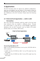
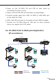
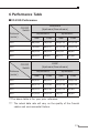
4.2 VC-232G Point to Multi-point Application
(IP surveillance)
VC-232G
(CO)
VC-232G
(CO)
VC-232G
(CPE)
VC-232G
(CPE)
NVR
IP Camera
Monitor
DC
DC
DC
DC
DC
Power Line (DC)
1000BASE-T UTP
Coaxial Cable
Coax.
Video Line
Video
Video
L2+ Switch
Coax.Coax.
IP Camera