Gigabit Ethernet over VDSL2 Converter/Bridge VC-231G/VC-234G User’s Manual
Trademarks Copyright © PLANET Technology Corp. 2017. Contents are subject to revision without prior notice. PLANET is a registered trademark of PLANET Technology Corp. All other trademarks belong to their respective owners.
communications. Operation of this equipment in a residential area is likely to cause harmful interference in which case the user will be required to correct the interference at his own expense. CE Mark Warning This is a Class A product. In a domestic environment, this product may cause radio interference, in which case the user may be required to take adequate measures. Energy Saving Note of the Device This power required device does not support Standby mode operation.
Table of Contents 1. Package Contents............................................................... 5 2. Product Features................................................................ 6 3. Hardware Introduction........................................................ 8 3.1 Front Panel and LED Indicators..................................... 8 3.2 Rear Panel and Mode DIP Switch.................................11 3.3 Power Information......................................................15 4.
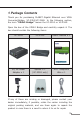
1. Package Contents Thank you for purchasing PLANET Gigabit Ethernet over VDSL Converter/Bridge, VC-231G/VC-234G. In the following section, the term “VDSL2 Bridge” means the VC-231G or VC-234G Open the box of the VDSL2 Bridge and carefully unpack it.
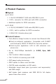
2.
¾¾ Voice and data communication can be shared simultaneously based on the existing telephone wire with distance up to 1.4km ¾¾ Supports a packet size of up to 9K bytes; IEEE 802.
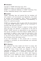
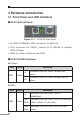
3. Hardware Introduction 3.1 Front Panel and LED Indicators VC-231G Front Panel VDSL 1000 TP 100 PWR CO VC-231G CPE 10/100/1000 Ethernet over VDSL 2 Converter Figure 3-1-1: VC-231G Front Panel ¾¾ 10/100/1000BASE-T RJ45 connector for Ethernet ¾¾ RJ11 connector for VDSL2; connect to IP DSLAM or another VDSL2 Bridge ¾¾ LEDs for power, Ethernet and VDSL VC-231G LED Indicators System LED PWR Color Function Lit Indicates that the VDSL2 Bridge has power.
CO Green Lit Indicates the VDSL2 Bridge is running in CO mode. CPE Green Lit Indicates the VDSL2 Bridge is running in CPE mode. 10/100/1000BASE-T Port LED Color Function Lit 1000 100 Indicates that the port is operating at 1000Mbps. Indicates that the VDSL2 Bridge is Green Blink actively sending or receiving data over that port at 1000Mbps. Off Indicates that the port is link down or 10/100Mbps. Lit Indicates that the port is operating at 100Mbps or 10Mbps.
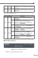
VC-234G LED Indicators System LED PWR Color Function Lit Indicates that the VDSL2 Bridge has power. Off Indicates that the VDSL2 Bridge has no power. Lit Indicates that the VDSL link is established. Green VDSL LED VDSL Color Green Function Fast Indicates that the VDSL link is at training Blink status (about 10 seconds). Slow Indicates that the VDSL link is at idle Blink status. CO Green Lit Indicates the VDSL2 Bridge is running in CO mode.
Lit 100 Indicates that the port is operating at 100Mbps or 10Mbps. Indicates that the VDSL2 Bridge is Green Blink actively sending or receiving data over that port at 100Mbps or 10Mbps. Off Indicates that the port is link down or 1000Mbps. 3.2 Rear Panel and Mode DIP Switch VC-231G Rear Panel 5V DC Mode Tran. Band CO G.INP Asym. 12dB CPE Interleave Sym.
¾¾ One RJ11 connector for telephone or PBX POTS ¾¾ DIP switch ¾¾ DC jack (DC input) for power adapter DC Power Jack The VC-234G/VC-231G requires 5V DC, 2A power input, which conforms to the bundled AC adapter. Should you have the issue of power connection, please contact your local sales representative. Note Note The device is a power-required device, meaning it will not work till it is powered.
DIP-1 Mode DIP-2 DIP-3 DIP-4 Transmission Band Profile SNR Margin OFF CO G.INP Asymmetric 12dB ON (default) CPE Interleave Symmetric 8dB DIP-1: Mode (CO/CPE) CO (Central Office) The Master device mode, usually the CO device, is located at the data center of ISP or enterprise to link to the backbone. CPE (Customer Premises Equipment) The Slave device mode, usually the CPE device, is located at branch office, home or remote side as the long reach data receiver.
DIP-3: Band Profile (Asymmetric/Symmetric) Asymmetric Asymmetric mode provides more bandwidth than the other side. This mode provides the highest bandwidth in short range. Symmetric With G.997 band plan supported, symmetric mode can provide almost the same rate of downstream and upstream. DIP-4: SNR (Signal Noise Ratio) Margin When the SNR margin is selected, the system provides 12dB/8dB SNR margin for across all usable loop lengths.
3.3 Power Information The central posts of the VC-231G’s and VC-234G’s power jacks measure 2.5mm wide that require +5VDC power input. They conform to the bundled AC-DC adapter and Planet’s media chassis. Should you have the issue of power connection, please contact your local sales representative. Please keep the AC-DC adapter as a spare part when the VC-231G is installed to a media chassis. 2.5mm Width of DC Receptacle: 2.5mm +5V for each slot DC receptacle is 2.
4. Connecting And Using The VDSL2 Bridge The Ethernet to VDSL2 Bridge does not require any software configuration. Users can immediately use any feature of this product simply by putting the plug in the receptacle and turning it on. There is some key limitation on the VDSL2 Bridge.
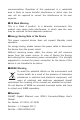
RJ11 Line Cord Phone Splitter RJ11 Line Cord VDSL 1000 100 VC-231G PWR CO VC-231G CPE RJ11 Phone Jack TP 10/100/1000 Ethernet over VDSL 2 Converter RJ45 Cat.5 Twisted-pair Cable Switch IP Camera IP TV Wireless PC Laptop 1000BASE-T UTP Telephone wire Phone RJ11 Phone Jack VC-234G 12dB Asym. G.INP CO 5V DC LAN 10/100/1000T OFF ON 1 ON 2 3 4 8dB Sym.
4.1 Point-to-Point Application -- LAN to LAN Connection Two sets of the VDSL2 Bridge could be used to link two local Area networks that are located in a different place. Through the normal telephone line, it could be set up a 150/150Mbps (G.INP, Sym, 8dB) symmetric backbone, but one VDSL2 Bridge must be Master (CO mode) and the other one is Slave (CPE mode).
Refer to the following procedures to set up the VC-234G/ VC-231G LAN to LAN connection. 1. [LAN1] Set the VC-234G/VC-231G at LAN 1 to be CO mode from the DIP switch. 2. [LAN2] Set the VC-234G/VC-231G at LAN 2 to be CPE mode from the DIP switch. 3. Power on the VC-234G/VC-231G CO and CPE at both sides by connecting its power source. 4. Power LED will illuminate. 5. Connect VDSL line from another VDSL device to RJ11 VDSL port of the VC-234G/VC-231G. 6.
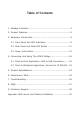
Multi-LAN Connection Ethernet Telephone Network Telephone wire Main office/PBX, Telco CO, Wire Closet Phone Telephone wire Phone Ethernet over VDSL2 and Telephone Network Splitter VDSL2 Switch (Multi-port CO) VDSL2 Telephone wire Main office/PBX, Telco CO, Wire Closet Phone Switch VC-231G VC-234G VDSL2 UP to 1.4km Phone 100BASE-TX UTP 1000BASE-T UTP Telephone wire VDSL2 VDSL2 Refer to the following procedure to set up the VC-234G/ VC-231G to IP DSLAM connection. 1.
4. Power LED will illuminate. 5. Connect VDSL line from IP DSLAM/VDSL2 switch to RJ11 VDSL port of the VC-234G/VC-231G. 6. VDSL LNK LED will blink to illuminate. 7. Connect telephone to the RJ11 Phone port of the VC-234G/ VC-231G. 8. Connect the VC-234G/VC-231G Ethernet LAN port to other network device via regular Cat.5 UTP cable.
5. Product Specifications Product VC-231G VC-234G Hardware Specifications LAN Ports 1 10/100/1000BASE-T RJ45 auto-MDI/MDI-X ports VDSL Port 1 VDSL2 RJ11 female phone jack Twisted-pair telephone wires (AWG24 or better) up to 1.4km Phone Port Additional splitter for POTS connection 1 RJ11, built-in splitters for POTS connection Dimensions (W x D x H) 97 x 70 x 26 mm 154.6 x 86.0 x 26.
Switch Specifications Switch Processing Scheme Store-and-Forward Address Table 2K entries Flow Control Back pressure for half duplex IEEE 802.3x pause frame for full duplex Jumbo Packet Size 9K bytes System Specifications VDSL Compliance VDSL-DMT ITU-T G.993.1 VDSL ITU-T G.997.1 ITU-T G.993.2 VDSL2 (Profile 17a/30a Support) ITU-T G.993.5 G. Vectoring ITU-T G.998 G.INP ADSL Compliance Capable of ADSL2/2+ standard ITU G.992.3 G.dmt.bis ITU G.992.5 G.dmt.
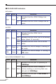
6. Performance Table VC-231G Performance, unit: Mbps Interleave (Downstream/Upstream) Distance (meter) Asymmetric 8dB 12dB Symmetric 8dB 12dB 200m 190/87 178/84 147/139 135/127 400m 161/60 143/53 112/110 96/96 600m 118/36 99/32 75/73 61/59 800m 59/24 48/22 44/44 40/40 1000m 47/7 41/5 26/25 23/18 1200m 39/4 33/3 24/13 22/9 1400m 25/4 23/3 20/9 16/7 G.
VC-234G Performance, unit: Mbps Interleave (Downstream/Upstream) Distance (meter) Asymmetric 8dB 12dB Symmetric 8dB 12dB 200m 193/89 180/80 142/139 137/129 400m 164/69 145/57 116/118 99/102 600m 112/39 95/32 70/73 54/61 800m 70/14 60/13 50/40 41/35 1000m 46/7 39/6 24/24 22/19 1200m 37/4 31/3 21/13 19/8 1400m 21/4 18/2 10/6 7/3 G.
7. Troubleshooting SYMPTOM: VDSL LNK LED does not light up after wire is connected to the VDSL port. CHECKPOINT: 1. Verify the length of the wire (not more than 1.4km) connected between the VC-231G and the VC-234G. Please also try to adjust the DIP switch or the VC-231G/VC-234G to the other SNR mode. 2. Please note you must use one VC-231G/VC-234G in CO mode and the other VC-231G/VC-234G in CPE mode to make connection to each other work.
8. FAQs Q1: What is VDSL2? A1: VDSL2 (Very High-Bit-Rate Digital Subscriber Line 2), G.993.2, is the newest and most advanced standard of xDSL broadband wire line communications. Designed to support the wide deployment of Triple Play services such as voice, data, high definition television (HDTV) and interactive gaming, VDSL2 enables operators and carrier to gradually, flexibly, and cost efficiently upgrade the existing xDSL-infrastructure.
Q4: What is the best date rate for the VC-231G/VC-234G? A4: The best data rate of the VC-231G is up to 190Mbps/100Mbps (downstream/upstream) in asymmetric mode and 150Mbps/150Mbps in symmetric mode over a distance of 200 meters. The VC-234G provides a data rate of up to 200Mbps/100Mbps (downstream/upstream) in asymmetric mode and 150Mbps/150Mbps in symmetric mode over a distance of 200 meters.
9. Customer Support Thank you for purchasing PLANET products. You can browse our online FAQ resource on PLANET Website first to check if it could solve your issue. If you need more support information, please contact PLANET switch support team. PLANET online FAQ: http://www.planet.com.tw/en/support/faq.php?type=1 Switch support team mail address: support@planet.com.tw Copyright PLANET Technology Corp. 2017. Contents are subject to revision without prior notice.
Appendix: Wall-mount and Chassis Installation This part describes how to install your VDSL2 Bridge and make connections to it. Please read the following topics and perform the procedures in the order being presented. Wall-mount Installation Step 1: Please find the wall that can mount the VC-234G/ VC-231G Step 2: Screw two screws on the wall. Step 3: Hang the VC-234G/VC-231G on the screws from the wall. Step 4: Refer to chapter 3.3 Power Information for power supply to the VC-234G/VC-231G.
G.INP 8dB SNR Sym. Band Tran. Interleave CPE 5V DC CO VDSL 2 Converter Mode Ethernet over RJ45 UTP Cable Asym. 12dB 1 ON 2 3 4 OFF RJ11 ON VC-231G Switch Bottom Side 90mm 90mm Ø2mm Ø7mm Ø2mm Ø7mm VC-234G Switch Bottom Side VC-234G Switch Bottom Side RJ45 UTP Cable Sym.8dB CPE Inter OFF ON 5V DC Phone VDSL 4 1 2 3 T 10/100/1000 LAN 12dB Asym. CO G.INP RJ45 UTP Cable Sym.8dB CPE Inter OFF ON 5V DC 31 Phone 12dB Asym. CO G.
Chassis Installation and Rack Mounting (VC-231G) To install the Ethernet over VDSL2 Converter in a 10-inch or 19-inch Converter Chassis with standard rack, follow the instructions described below. Step 1: Place your VC-231G on a hard flat surface, with the front panel positioned towards your front side. Step 2: Carefully slide in the module until it is fully and firmly fitted into the slot of the converter chassis.