Ethernet over VDSL2 Converter VC-201 / VC-202 User’s Manual
Trademarks Copyright © PLANET Technology Corp. 2007 Contents subject to revision without prior notice. PLANET is a registered trademark of PLANET Technology Corp. The information in this manual is subject to change without notice. All other trademarks belong to their respective owners.
If you find information in this manual that is incorrect, misleading, or incomplete, we would appreciate your comments and suggestions. FCC Warning This equipment has been tested and found to comply with the regulations for a Class A digital device, pursuant to Part 15 of the FCC Rules. These limits are designed to provide reasonable protection against harmful interference when the equipment is operated in a commercial environment.
WEEE Warning To avoid the potential effects on the environment and human health as a result of the presence of hazardous substances in electrical and electronic equipment, end users of electrical and electronic equipment should understand the meaning of the crossedout wheeled bin symbol. Do not dispose of WEEE as unsorted municipal waste and have to collect such WEEE separately. Revision Ethernet Over VDSL2 Converter User’s Manual For Models: VC-201 / VC-202 Rev 1.0 (September 2007) Part No.
TABLE OF CONTENTS 1. Introduction................................................................7 1.1 Checklist..............................................................7 1.2 Introduction to Ethernet over VDSL2 Converter.......7 1.3 Key Features...................................................... 10 1.4 Specifications..................................................... 11 2. Hardware Description................................................. 14 2.1 Front Panel......................................
3.2.2 Connecting Multiple PCs to an Ethernet LAN...22 3.3 Connecting VC-202............................................. 23 3.3.1 Connecting Standalone IP device................ 23 3.3.2 Connecting Multiple PCs to an Ethernet LAN...24 3.4 Chassis Installation and Rack Mounting................ 25 4. POWER INFORMATION............................................... 27 5. Troubleshooting......................................................... 28 6. FAQ ...........................................
1. Introduction 1.1 Checklist Check the contents of your package for following parts: ● Ethernet over VDSL2 Converter ● Power Adapter ● RJ-11 Telephone line (VC-201 only) ● User’s Manual If any of these pieces are missing or damaged, please contact your dealer immediately, if possible, retain the carton including the original packing material, and use them against to repack the product in case there is a need to return it to us for repair. 1.
means upstream and downstream rate are the same or similar) – the VDSL port can be RJ-11 connectors or BNC connector. The VC-201/VC-202 can be set to CO mode or CPE mode via a DIP switch. When the VC-20X-CO is used to connect to the other VC-20X-CPE as a standalone pair, up to 100/55Mbps asymmetric data rate within 200m and up to 30/6Mbps asymmetric data rate at 1km. This capability is ideal for use as an Ethernet extender for your existing Ethernet network.
1.3 Key Features The converter provides the following key features: ● Cost-effect VDSL2 CO/CPE bridge solution ● One box design, CO/CPE selectable via DIP Switch ● Complies with IEEE 802.3, IEEE 802.3u and IEEE 802.3x standards ● DMT (Discrete Multi-Tone) line coding ● Half duplex Back pressure and IEEE 802.
1.4 Specifications Product VC-201 VC-202 Hardware Specification 10/100Base-TX 1 RJ-45, Auto-negotiation and Auto-MDI/MDI-X VDSL 1 RJ-11, female Phone Jack 1 BNC, female connector PHONE 1 RJ-11, Built-in splitters for POTS/ISDN connection - Ports DIP Switch 4 position DIP switch Functionality • • • • Encoding • VDSL-DM - ITU-T G.993.1 VDSL - ITU-T G.997.1 - ITU-T G.993.
LED Indicators Ethernet Cabling VDSL Performance* (Down Stream / Up Stream) Power Requirement • One Power, • 3 for RJ-11/VDSL2 WAN : - Green, LNK/ACT - Green, CO mode - Green, CPE mode • 2 for per RJ-45 10/100Base-TX port - Green, LNK/ACT. - Green, Speed • 10Base-T: 2-pair UTP Cat.3,4,5 up to 100m (328ft) • 100Base-TX: 2-pair UTP Cat.5, up to 100m (328ft) Twisted-pair telephone 50 ohm, RG58A/U, or ISDN wires RG58C/U, RG58/U or (AWG24 or better) up equivalent to 6.
Operating Humidity 10% to 90% , relative humidity, noncondensing Storage Humidity 10% to 90% , relative humidity, noncondensing Standard Conformance Regulation Compliance FCC Part 15 Class A, CE Standards Compliance IEEE 802.3 10BASE-T IEEE 802.3u 100BASE-TX ITU-T - G.993.1 (VDSL) - G.997.1 - G.993.2 VDSL2 (Profile 12a Support), Annex A * The actual data rate will vary on the quality of the copper wire or coaxial cable and environment factors.
2. Hardware Description VC-201 provides 2 RJ-11 ports for voice connection (like telephone or ISDN) and for network line connection. VC-202 provides 1 BNC connector and supports 50 ohm cable with distance of up to 1.6km Both VC-201 and VC-202 provide 1 RJ-45 ports for two different running speed –10Mbps, 100Mbps, in the same converter and automatically distinguish the speed of incoming connection. This section describes the hardware features of these Converters.
● VC-202 Front Panel 2.1.1 LED indicators The rich diagnostic LEDs on the front panel can provide the operating status of individual port and whole system. ● System LED PWR Color Green Function Lit: Power ON Off: Power OFF ● VDSL LED Color Function Lit: Indicate that the VDSL link is established.
● 10/100Base-TX Port LED Color Function Lit: Indicate that the port is link up. Indicate that the converter is actively LNK/ Green Blink: sending or receiving data over that port ACT 100 Off: Indicate that the port is link down Lit: Indicate that the port is operating at 100Mbps. Off: Indicate that the port is link down or 10Mbps. Green 2.2 The Rear Panel The rear panel of the converter is shown below. ● VC-201 / VC-202 Rear Panel 2.2.
distance of connectivity. The following is the summary table of transmission setting, bandwidth and distance extensibility tested for AWG 24 (0.5mm) twisted-pair without noise and cross talk. DIP-1 DIP-2 DIP-3 DIP-4 Mode Channel Rate Limit SNR OFF CO Interleave 50/20 Mbps 9dB ON(default) CPE Fast No Limit 6dB ● CO / CPE ▪ CO (Central Office) – the Master device mode, usually the CO device will be located at the data center of ISP or enterprise to link to the backbone.
● Rate Limit: (For CO Mode only) User has the ability to select fixed data rate. When Rate Limit is selected, the system will lock the date rate at 50Mbps/20Mbps whenever the calculated SNR margin is higher than 9 dB. This gives best system stability. ● Target SNR (Signal Noise Ratio) Margin: (For CO Mode only) When fixed SNR margin is selected, the system will maintain the SNR margin at 9 dB across all usable loop length. Please power off the converter transmission mode adjustment.
3. Installing and Using VDSL Converter 3.1 Install the Ethernet Over VDSL2 Converter The Converter does not require any software configuration. Users can immediately use any feature of this product simply by attached the cables and plug power on. There is some key limitation on the Ethernet over VDSL2 converter. Please check the following items: ● The device is used for Point-to-Point connection only (Master device to Slave device) and allows data and voice work on the same telephone or ISDN lines.
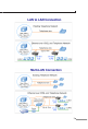
asymmetric backbone, but one converter must be Master (CO mode) and the other one is Slave (CPE mode). Figure 3-1: VC-201 LAN to LAN connection 3.1.2 VC-201 Connect to Multi-Port Master In order, to built up a local Internet in apartment, hotel, campus and hospitality environment.
● Air flow around the unit and through the vents in the side of the case is not restricted (company recommend that you provide a minimum of 25mm inch clearance) To prolong the operational life of your units: ● Do not place objects on top of any unit or stack 3.2 Connecting VC-201 3.2.1 Connecting Standalone PC Refer to the following procedures to setup the VC-201 to a standalone PC. 1. Set the VC-201 to be CO mode or CPE mode from the DIP switch at the rear panel. 2.
Figure 3-2: Connecting Standalone PC 3.2.2 Connecting Multiple PCs to an Ethernet LAN Refer to the following procedures to setup the VC-201 to an Ethernet LAN. 1. Set the VC-201 to be CO mode or CPE mode from the DIP switch at the rear panel. 2. Power on the VC-201 by connecting its power source. 3. Power LED will illuminate. 4. Connect VDSL line from another VDSL device to VDSL port of the VC-201. 5. LNK LED will illuminate. 6. Connect telephone to the PHONE port. 7.
Figure 3-3: Connecting Multiple PCs to an Ethernet LAN Note Please refer to your Ethernet device User’s Manual for the device’s set up information. 3.3 Connecting VC-202 3.3.1 Connecting Standalone IP device Refer to the following procedures to setup the VC-202 to a standalone PC. 1. Set the VC-202 to be CO mode or CPE mode from the DIP switch at the rear panel. 2. Power on the VC-202 by connecting its power source. 3. Power LED will illuminate. 4.
5. LNK LED will from blinking to illuminate. 6. Connect Ethernet port to Ethernet device via regular Cat. 5 cable. Figure 3-4: Connecting Standalone IP device 3.3.2 Connecting Multiple PCs to an Ethernet LAN Refer to the following procedures to setup the VC-202 to an Ethernet LAN. 1. Set the VC-202 to be CO mode or CPE mode from the DIP switch at the rear panel. 2. Power on the VC-202 by connecting its power source. 3. Power LED will illuminate. 4.
Figure 3-5: Connecting Multiple PCs to an Ethernet LAN Note Please refer to your Ethernet device User’s Manual for the device’s set up information. 3.4 Chassis Installation and Rack Mounting To install the VDSL2 Converter in a 10-inch or 19-inch Converter Chassis with standard rack, follow the instructions described below. Step 1: Place your VC-201/VC-202 on a hard flat surface, with the front panel positioned towards your front side.
Figure 3-6: Insert a VDSL2 converter into an available slot Step 3: Attach a rack-mount bracket to each side of the Chassis with supplied screws attached to the package. Step 4: After the brackets are attached to the Converter Chassis, use suitable screws to securely attach the brackets to the rack Step 5: Proceed with the steps 4 and steps 5 of session 3.2 Stand-alone Installation to connect the network cabling and supply power to your Converter Chassis.
4. POWER INFORMATION The power jack of VC-20x is with 2.5mm in the central post and required +5VDC power input. It will conform to the bundled AC-DC adapter and Planet’s Media Chassis. Should you have the problem to make the power connection, please contact your local sales representative. Please keep the AC-DC adapter as spare parts when your VC-20X is installed to a Media Chassis. 2.5mm DC Receptacle 2.5mm +5V for each slot DC receptacle is 2.5mm wide that conforms to and matches the VDSL2 Converter 2.
5. Troubleshooting SYMPTOM: VDSL LNK LED does not lit after wire is connected to the VDSL port. CHECKPOINT: 1. Verify the length of the wire connected between two VC201 is not more than 1.5km. Please also try to adjust the DIP switch or VC-201 to other SNR mode. 2. Please note you must use one VC-201 with CO mode and the other VC-201 with CPE mode, connect to each other to make it work. SYMPTOM: TP LNK/ACT LED does not lit after cable is connected to the port. CHECKPOINT: 1. Verify you are using the Cat.
5. The connecting cable is good and with correct type. 6. The connecting device, including any network adapter is functional.
6. FAQ Q1: What voltage that VC-201/VC-202 used? A1: 5VDC, 2A Q2: What is VDSL2? A2: VDSL2 (Very High-Bit-Rate Digital Subscriber Line 2), G.993.2 is the newest and most advanced standard of xDSL broadband wire line communications. Designed to support the wide deployment of Triple Play services such as voice, data, high definition television (HDTV) and interactive gaming, VDSL2 enable operators and carrier to gradually, flexibly, and cost efficiently upgrade exiting xDSL-infrastructure.
Q6: Can VC-201 compatible with VC-200M / VC-200S? A6: Currently NO, although VC-201 and VC-200M/200S are base on ITU-T G.993.2 VDSL2, but with different chipset specification, so far they are not compatible with each other. Q7: What is SNR and what’s the effect? A7: In analog and digital communications, Signal-toNoise Ratio, often written SNR, is a measure of signal strength relative to background noise. The ratio is usually measured in decibels (dB).
This page is intentionally left blank