6-port + 2 Gigabit-slots VDSL Stackable Switch VC-1602 User’s Manual
Trademarks Copyright PLANET Technology Corp. 2003. Contents subject to revision without prior notice. PLANET is a registered trademark of PLANET Technology Corp. to their respective owners. All other trademarks belong Disclaimer PLANET Technology does not warrant that the hardware will work properly in all environments and applications, and makes no warranty and representation, either implied or expressed, with respect to the quality, performance, merchantability, or fitness for a particular purpose.
TABLE OF CONTENTS CHAPTER 1 INTRODUCTION .................................................................................................. 1 1.1 CHECKLIST ......................................................................................................................... 1 1.2 ABOUT THE SWITCH ............................................................................................................ 1 1.3 FEATURES .......................................................................................
Chapter 1 INTRODUCTION 1.1 Checklist Check the contents of your package for following parts: l VC-1602. l CD-ROM. l Quick Installation Guide l Power cord. l 19” rack-mount brackets. l RS-232 cable. If any of these pieces are missing or damaged, please contact your dealer immediately, if possible, retain the carton including the original packing material, and use them against to repack the product in case there is a need to return it to us for repair. 1.
1.3 Features w Cisco LRE CPE modem compatible w Complies with IEEE802.3 10Base-T, IEEE802.3u 100Base-TX, IEEE 802.3z 1000Base-SX/LX, IEEE 802.3ab 1000Base-T, IEEE 802.3x flow control, IEEE 802.1Q VLAN and 802.
EMC/EMI Management Interface Protocols and Standards Network Management FCC, CE Web, Console, Telnet and SNMP IEEE 802.3 (Ethernet) IEEE 802.3u (Fast Ethernet) IEEE 802.3z/802.3ab (Gigabit Ethernet) IEEE 802.3x (flow control) IEEE 802.1Q VLAN tag IEEE 802.
Chapter 2 HARDWARE INSTALLATION This section describes the hardware features and installation of these Switches. For easier management and control of the switch, familiarize yourself with its display indicators, and ports. Front panel illustrations in this chapter display the unit LED indicators. Before connecting any network device to the switch, read this chapter carefully.
Stack ports There are two stack ports on the front panel. One is IN and the other is OUT. When stacked, the IN port should connect to the other switch’s OUT port and the OUT port should connect to other switch’s IN out. You can just use normal Cat 5 or better cable with RJ-45 connector to stack. Only straight-through UTP/STP cable can be used. There is no Duplex Mode issue and the maximum distance between first and last switch is 800m. SWITCH ID Each switch on a stack must have a unique switch ID.
Wiring for VDSL ports The VDSL port of VC-1602 uses one RJ-21 (Telco 50) connector to connect up to 16 VDSL converters (VC-102S, VC-101S or Cisco LRE modem) through structured or unstructured wiring, such as existing telephone lines. The link between the VDSL switch port and each converter can reach speeds of up to 15/17 Mbps over distances of up to 5000 feet (1500 meters). You can hot swap the VDSL converters without powering down the switch or disrupting the other switch ports.
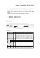
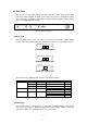
2.2 Rear Panel The rear panel of the switch indicates an AC inlet power socket, which accepts input power from 100 to 240VAC, 50-60Hz, one RS-232 console port for setting up the switch via a connection to a terminal or PC using a terminal emulation program, and two slide-in slots for installing additional modules. 17 100~240V AC 18 CONSOLE 9600, 8, N, 1 50 / 60Hz VC-1602 Switch front panel Slide-in slots The two slide-in slots on the rear panel are reserved for following optional gigabit modules.
♦ DCE ♦ 9600 (Fix baud rate) ♦ n (No parity checking) ♦ 8 (8 Data bits) ♦ 1 (1 stop bit) ♦ None (No flow control) You can use a normal RS-232 cable and connect to the console port on the device. After the connection, you can run any terminal emulation program (Hyper Terminal, Winterm, Telix, and so on) to enter the startup screen of the device.
1. 2. 3. Never stack unit more than eight sets high if freestanding. Do not place objects on top of any unit or stack. Do not obstruct any vents at the sides of the case. Rack-mount Installation The switch may standalone, or may be mounted in a standard 19-inch equipment rack. Rack mounting produces an orderly installation when you have a number of related network devices. The switch is supplied with rack mounting brackets and screws. These are used for rack mounting the unit.
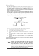
2.4 Stack Installation There are two RJ-45 ports on the front panel for proprietary management stack. Only straight-through UTP/STP cable can be used. Plug one end of the cable in the “IN” port and the other end to the ”OUT” port of next device. Repeat the step for every device in the stack cluster, then ending at last switch. ëNote Before management stacking, be sure of every device uses a unique “SWITCH ID”, or the management stack will not work. The switch with least SWITCH ID will become Master.
Chapter 3 CONSOLE AND TELNET MANAGEMENT 3.1 Connect To PC by RS-232 serial Cable ëNote If you have stacked several switches together, make sure you are working on Master switch (switch with least Switch ID). Other slave switches’ management interface allows only viewing the configuration by “guest” account. To configure the system, connect the provided serial cable to a COM port on a PC or notebook computer and to serial (console) port of the device.
1. Be Sure of the switch is configured with an IP address and the switch is reachable from a PC. 2. Start the Telnet program on a PC and connect to the switch. The management interface is exactly the same with RS-232 console management except the “root” priviledge is not supported. 3.3 Main Menu After you enter the switch’s console interface by RS-232 cable or telnet, the following page is shown. Please enter username and password to access VC-1602.
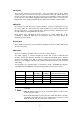
2. Management Setup 2. System Information Show detail system information of each switch including their hardware, software version, system up time, system contact, device name, device location and system management capabilities. 3. System Configuration Modify system contact, device name and device location of each switch on the stack. 1. Network Configuration Configure each switch’s IP address, subnet mask and default gateway. 2.
8. Priority Tag Define the 802.1p tag mapping and the service rule. Please refer to section 4.13 for detail. This menu allows you to configure the password of root, admin and guest account. Only root account has the right to enter this menu. 4. User Authentication 1. System Restart Restart the switch. Two options are available: cold start and warm start. 2. Default Factory Reset Reset the switch back to factory default settings. 3. Timeout Interval Setup Configure the telnet timeout interval. 4.
CHAPTER 4. WEB MANAGEMENT 4.1 Start A Web Browser Session The Web Interface of VC-1602 is coded by Java Applet and running on the JavaTM Virtual Machine (JVM) version 1.3.1 platform. You should configure the management station with an IP address and subnet mask compatible with VC-1602 for accessing it. Also, the management station should be well configured and connected to Internet for automatically downloading (upgrading) the suitable JVM through Internet from http://java.sun.com.
4.2 Stack Main Page The stack main page contains two options: Topology This screen displays one or more switches of the management stack. Basic properties can be read by the screen, including Hardware characteristic, Device Name, Up time, Master and Slave relationship. Also, by mouse clicking listed items can enter for further operation.
4.3 Switch Main Page Switch Main Page appears after you click one of the switch(es) on the topology page. There are 8 function button listed on top: Home, Save, Default, Reboot, Ping, Telnet, Contact, and Upgrade. Shortcut to back to stack home page Save the current setting to Non-volatile Memory. The difference between and is that Apply applies settings right away but saves the values in the system memory.
You can specify switch(es) and reboot it. Warm Boot Cold Boot Reboot the switch in a short time. Boot the switch and with fully Power On Self Test (POST). The system is completely checked but spends much time. The Ping is a commonly used tool to detect the remote host or IP address exists or not. Moreover, network status also can be known by the ratio of packets Reply and Loss. By simply clicking the button, the Telnet program implements and displays login screen.
WEB Upload w Select Device ID and “WEB Upload” radio button then click OK. w Specify the file path by clicking Browse button and click Start. TFTP Download 1. Select Device ID and “TFTP Download” radio button then click OK. 2. Enter the TFTP server’s IP address in Server IP field. 3. Enter file name in File Name field. Click Start button to download the code and system update with it automatically Local File Transfer 1. Select Device ID and “Local File Transfer” radio button then click OK. 2.
Device The shortcut to go to another member switch in the management stack. 4.4 Device Configuration Panel Display MASTER LED SWITCH ID Port Link status LED STATUS LED Slide-in Modules RJ-21 VDSL ports Network Configuration IP Address: IP address of this device. Subnet Mask: Subnet Mask of your network. Gateway IP: IP address of Gateway. Device Information Name: Naming the system (optional). Contact: Who the System administrator is (optional).
4.5 Topology Info This page displays information about the switch(es), such as Device ID, Hardware version, Boot-Up version, POST version, Runtime version (Firmware version), JAVA Applet version (Web User Interface version), Device Name and Device Location. When management stack persist, by the Device ID, all the members are transparently listed. 4.6 Ports Information It is a ports’ configurations summary table.
Configuration Port attributes can be setup in this page. Setup Port Attributes - VDSL port 1. Click the “Name” column of the port. Enter a name for identification, like ‘Richard’; and press Enter. 2. Leave the “Admin” column ‘Enable’ value to make the port to be in operation or ’Disable’ to pause it. 3. Select Profile. 5 profiles available, ANSI, ETSI, VE-5, VE-10 and VE-15. Please check chapter 2.1 for the data rate of each speed and their maximum connection distance. 4.
Duplicate Port Attributes Click “Duplicate” button, the dialogue screen appears. 1. Select Source Port (for example Port 1). 2. Select Target Port, click 3. Select the port attributes you want to duplicate. 4. Click 5. Click Apply button to apply settings. 6. As the following result, port 1 is duplicated to port 2, 3, 4, 5 accompany with specified attributes. OK All for select all (for example Port 2, 3, 4, 5). to submit values.
ëNote Also accomplished by simply mouse right-click the port on the ‘Panel Display’ then select ‘Copy Setting’ to duplicate port properties and select ’Past Setting’ when point at destination port. Statistic The statistics function provides the following 3 pages for various traffic information of each port. There is a Clear button on the bottom of each page for you to clear the statistic data and recount again.
Location Search A denominate port can be searched by its given name (Match whole word only). OAM-Like OAM (Operation Administration Maintenance) is a powerful tool indispensable to telecommunication technician for troubleshooting and diagnosis. Experienced technicians can perform looping tests with OAM tool to discover abnormal nodes or segments. The OAM-Like is a simplified-OAM, which features the switch to run looping tests while remote administer by simply mouse clicking.
4.7 Security This is reserved for future use. 4.8 SNMP Simple Network Management Protocol (SNMP) is a communication protocol for managing devices on a network. It is commonly used for network administrators to communicate with multiple devices (hub, switch, router ……) for configuring and monitoring while convenient for troubleshooting but no miscellaneous platform consideration. The built-in SNMP is an agent, which watches the status of it self.
To Modify a Community 1. Select one community you want to modify in the “Current” column 2. The “New” column lists the corresponding values; please modify it 3. Click Modify button to update the entry Trap Manager Trap Manager specifies the Network Management Stations (NMS) that will receive trap messages from the SNMP agent and can up to 5 entries.
Trap Filtering Check the “Enable” boxes by mouse clicking to receive a notice when corresponding event occurs. 4.9 VLAN The VLAN is a group of ports that may spread around the network but communicate as though they belong to one subnet. By using VLAN, all ports can be reorganized into separate broadcast domains for security reasons and reduce bandwidth occupation instead of using routers to divide whole network into subnets.
To remove a VLAN group 1. Select a VLAN group you want to remove from the “Current” list. 2. Click Remove>> button to remove it. Attention: 1. If a removed port is no longer belonged to any other group, it is temporarily disabled because no one can communicate with it. 2. If one port’s PVID is equal to this VLAN ID, removing this VLAN group will not allow until you change it. To modify a VLAN group 1. Select a VLAN group you want to modify from the current list 2.
VLAN Port Configuration When the VLAN-enabled switch receives an untagged packet, the packet will be sent to the port’s default VLAN according to the PVID (port VLAN ID) of the receiving port. To change the PVID 1. Double click the “PVID” column of a port. 2. Input a new VLAN ID (1~255). 3. Press “Enter” to submit the value. 4. Click Apply button to apply it. ëNote 1. All the ports are default as members of VLAN 1 and assigned PVID 1. 2.
Click All Independent button then all the ports will be divided into separated subnets (totally 18 subnets). Every port can belong to different Port Group VLANs simultaneously without limitation. 4.10 Address Table The address table is the learning table, which is composed of many entries and is the most important base to do packet filtering and forwarding. MAC Address List Choose the port you preferred to view the address table and click “Refresh” button, the MAC address table will be list.
4.11 Mirror Port mirror is used to mirror traffic from source port to a target port for analysis. Only 2 ports can be monitored (mirrored) simultaneously to 1 sniffer port (target port). (Note that the target port must be in the same VLAN as the source port). 1. Click “Active” radio button to activate port mirror. 2. Select ‘Monitored Ports’ (up to 2 ports). 3. Click ‘Sniffer Port’ combo box and select a sniffer port (target port) and click “Apply” to apply. 4.
2:1 Send 2 high priority packets, then 1 low priority packet 3:1 Send 3 high priority packets, then 1 low priority packet 4:1 Send 4 high priority packets, then 1 low priority packet 5:1 Send 5 high priority packets, then 1 low priority packet 6:1 Send 6 high priority packets, then 1 low priority packet 7:1 Send 7 high priority packets, then 1 low priority packet - 33 -
CHAPTER 5. TROUBESHOOTING This chapter contains information to help you solve problems. If VC-1602 is not functioning properly, make sure the Switch was set up according to instructions in this manual. The port is connected but the port LED is not lit Solution: Check the following items: 1. The switch and the connected device’s power are on or not. 2. The connecting cable is good and with correct type. 3. The cable is firmly seated in its connectors in the switch and in the associated device. 4.
APPENDIX A A.1 Switch‘s RJ-45 Pin Assignments 1000Mbps, 1000Base T Contact MDI MDI-X 1 BI_DA+ BI_DB+ 2 BI_DA- BI_DB- 3 BI_DB+ BI_DA+ 4 BI_DC+ BI_DD+ 5 BI_DC- BI_DD- 6 BI_DB- BI_DA- 7 BI_DD+ BI_DC+ 8 BI_DD- BI_DC- Implicit implementation of the crossover function within a twisted-pair cable, or at a wiring panel, while not expressly forbidden, is beyond the scope of this standard. A.
A.3 RJ-45 cable pin assignment 6 321 6 321 6 3 21 A.4 RJ-21 Connector pin out 25 1 50 26 The above picture is the RJ-21 connector on VC-1602. connector pinouts.
22 Port 3, Tip 47 Port 3, Ring 23 Port 2, Tip 48 Port 2, Ring 24 Port 1, Tip 49 Port 1, Ring 25 No Connect 50 No Connect - 37 -