
Quick Guide

5
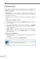
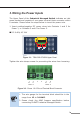
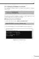
3. Wiring the Power Inputs
TheUpper Panelof the Industrial Managed Switch indicates an inlet
power socket and consists of one green terminal block connector within
6 contacts. Please follow the steps below to insert the power wire.
1.Insert positive/negative DC power wires into Contacts 1 and 2 for
Power1,orContacts5and6forPower2.
DC9-48V,AC24V
Max. Fault Alarm Loa ding: 24V, 1A
DI1 DO0 DO1DI0 GNDGND
V1+ V2+
PWR1
PWR2Alarm
DC Input: 9-48V
, 5A max.
AC Input: 24V
, 2A max.
1 2 3 4 5 6
1 2 3 4 5 6
Figure 3-1: TSN-6325-8T4S4X Upper Panel
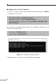
Tightenthewire-clampscrewsforpreventingthewiresfromloosening.
1 2 3 4 5 6
V+ V- V+ V-
Power 1 Power 2
Figure 3-2: Power 1 & 2 Pins of Terminal Block Connector
Note
1. The wire gauge for the terminal block should be in the
range from 12 to 24 AWG.
2. Please check the AWG Ampere specification before
connectingPLANETIndustrialManagedSwitch.