
Manual
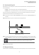
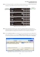
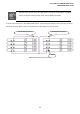


Table Of Contents
- 1. INTRODUTION
- 2. INSTALLATION
- 3. SWITCH MANAGEMENT
- 4. WEB CONFIGURATION
- 4.1 Main WEB PAGE
- 4.2 System
- 4.3 Simple Network Management Protocol
- 4.4 Port Management
- 4.5 Link Aggregation
- 4.6 VLAN
- 4.7 Rapid Spanning Tree Protocol
- 4.8 Quality of Service
- 4.9 Multicast
- 4.10 IEEE 802.1X Network Access Control
- 4.10.1 Understanding IEEE 802.1X Port-Based Authentication
- 4.10.2 802.1X System Configuration
- 4.10.3 802.1X and MAC-Based Authentication Port Configuration
- 4.10.4 802.1X Port Status
- 4.10.5 802.1X and MAC-Based Authentication Statistics
- 4.10.6 Windows Platform RADIUS Server Configuration
- 4.10.7 802.1X Client Configuration
- 4.11 Access Control Lists
- 4.12 Address Table
- 4.13 Port Security (To be Continued)
- 4.14 LLDP
- 4.15 Network Diagnastics
- 4.16 Stacking – SGSW-24040 / SGSW-24040R
- 4.17 Power over Ethernet (SGSW-24040P / SGSW-24040P4)
- 5. COMMAND LINE INTERFACE
- 6. Command Line Mode
- 6.1 System Command
- 6.2 Port Management Command
- 6.3 Link Aggregation Command
- 6.4 VLAN Configuration Command
- 6.5 Spanning Tree Protocol Command
- 6.6 Multicast Configuration Command
- 6.7 Quality of Service Command
- 6.8 802.1x Port Access Control Command
- 6.9 Access Control List Command
- 6.10 MAC Address Table Command
- 6.11 LLDP Command
- 6.12 Stack Management Command
- 6.13 Power over Ethernet Command
- 7. SWITCH OPERATION
- 8. POWER OVER ETHERNET OVERVIEW
- 9. TROUBLE SHOOTING
- APPENDEX A
- APPENDEX B : GLOSSARY
User’s Manual of WGSW-24040 Series
SGSW-24040/24240 Series
41
2.3.1 Connecting Stacking cable
Before attempting to connect stacking ports, verify that you have the required stack cables. The following cables are used to
connect stacked switches:
• CB-STX50: 50cm, Short stack cable –used to connect adjacent SGSW switches.
• CB-STX200: 200cm, Long / Redundant stack cable – used to connect the top and bottom SGSW switches of a stack.
There are two high-performance HDMI-like Stack ports on the rear panel for proprietary management stack. Only attached
PLANET CB-STX50 and CB-STX200 cross-overed HDMI cable can be used.
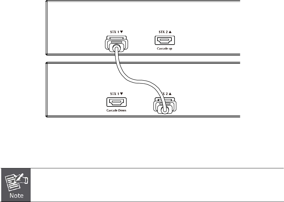
STEP-1: Plug one end of the cable in the “STX1 / Cascade Down” port and the other end to the ”STX2 / Cascade UP” port of
next device.
STEP-2: Repeat the step for every device in the stack cluster, then ending at last switch.
Figure 2-26 Stacking connection
STEP-3: If you wish to implement stack redundancy, use the long stack cable –CB-STX200 to connect the stack port marked
“STX1 / Cascade Down” on the bottom switch to the port marked “STX2 / Cascade Up” on the top switch of the stack.
The stack port is for management and data packets to be transmitted between other SGSW stackable
switches, the stack ports can’t be configured with Layer 2 features via management interface.
STEP-4: Power up the stack switches.
2.3.2 Management Stacking
The stack operation of the SGSW Managed Switch supports Plug and Play Stacking connection and auto stack configuration.