
Manual


Table Of Contents
- 1. INTRODUTION
- 2. INSTALLATION
- 3. SWITCH MANAGEMENT
- 4. WEB CONFIGURATION
- 4.1 Main WEB PAGE
- 4.2 System
- 4.3 Simple Network Management Protocol
- 4.4 Port Management
- 4.5 Link Aggregation
- 4.6 VLAN
- 4.7 Rapid Spanning Tree Protocol
- 4.8 Quality of Service
- 4.9 Multicast
- 4.10 IEEE 802.1X Network Access Control
- 4.10.1 Understanding IEEE 802.1X Port-Based Authentication
- 4.10.2 802.1X System Configuration
- 4.10.3 802.1X and MAC-Based Authentication Port Configuration
- 4.10.4 802.1X Port Status
- 4.10.5 802.1X and MAC-Based Authentication Statistics
- 4.10.6 Windows Platform RADIUS Server Configuration
- 4.10.7 802.1X Client Configuration
- 4.11 Access Control Lists
- 4.12 Address Table
- 4.13 Port Security (To be Continued)
- 4.14 LLDP
- 4.15 Network Diagnastics
- 4.16 Stacking – SGSW-24040 / SGSW-24040R
- 4.17 Power over Ethernet (SGSW-24040P / SGSW-24040P4)
- 5. COMMAND LINE INTERFACE
- 6. Command Line Mode
- 6.1 System Command
- 6.2 Port Management Command
- 6.3 Link Aggregation Command
- 6.4 VLAN Configuration Command
- 6.5 Spanning Tree Protocol Command
- 6.6 Multicast Configuration Command
- 6.7 Quality of Service Command
- 6.8 802.1x Port Access Control Command
- 6.9 Access Control List Command
- 6.10 MAC Address Table Command
- 6.11 LLDP Command
- 6.12 Stack Management Command
- 6.13 Power over Ethernet Command
- 7. SWITCH OPERATION
- 8. POWER OVER ETHERNET OVERVIEW
- 9. TROUBLE SHOOTING
- APPENDEX A
- APPENDEX B : GLOSSARY
User’s Manual of WGSW-24040 Series
SGSW-24040/24240 Series
39
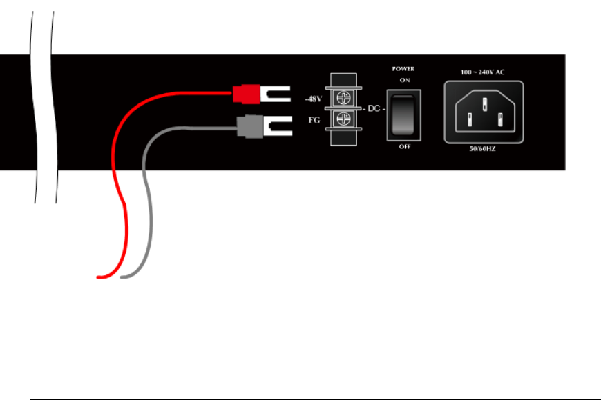
2.2.4 Connecting DC Power Supply – WGSW-24040R / SGSW-24040R
The WGSW-24040R and SGSW-24040R support -48VDC power input, connect the power cable to the switch at the input
terminal block.
1. The size of the two screws in the terminal block is M3.5.
2. The terminals are marked “-48V”, “FG“.
3. Loosen the two screws so you can slide the DC cable beneath it. Insert the DC cable into the connector first, and screw it
down tight.
4. Connect the power cable to the DC power supply. After power up or reset, the Managed Switch performs a cold start
procedure.
Figure 2-23 -48VDC connector
Warning:
Before connect the DC power cable to the input terminal block of Managed Switch, ensure that the
power switch in the “OFF” position and the DC power is OFF