
Manual
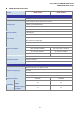
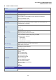
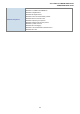


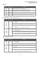
Table Of Contents
- 1. INTRODUTION
- 2. INSTALLATION
- 3. SWITCH MANAGEMENT
- 4. WEB CONFIGURATION
- 4.1 Main WEB PAGE
- 4.2 System
- 4.3 Simple Network Management Protocol
- 4.4 Port Management
- 4.5 Link Aggregation
- 4.6 VLAN
- 4.7 Rapid Spanning Tree Protocol
- 4.8 Quality of Service
- 4.9 Multicast
- 4.10 IEEE 802.1X Network Access Control
- 4.10.1 Understanding IEEE 802.1X Port-Based Authentication
- 4.10.2 802.1X System Configuration
- 4.10.3 802.1X and MAC-Based Authentication Port Configuration
- 4.10.4 802.1X Port Status
- 4.10.5 802.1X and MAC-Based Authentication Statistics
- 4.10.6 Windows Platform RADIUS Server Configuration
- 4.10.7 802.1X Client Configuration
- 4.11 Access Control Lists
- 4.12 Address Table
- 4.13 Port Security (To be Continued)
- 4.14 LLDP
- 4.15 Network Diagnastics
- 4.16 Stacking – SGSW-24040 / SGSW-24040R
- 4.17 Power over Ethernet (SGSW-24040P / SGSW-24040P4)
- 5. COMMAND LINE INTERFACE
- 6. Command Line Mode
- 6.1 System Command
- 6.2 Port Management Command
- 6.3 Link Aggregation Command
- 6.4 VLAN Configuration Command
- 6.5 Spanning Tree Protocol Command
- 6.6 Multicast Configuration Command
- 6.7 Quality of Service Command
- 6.8 802.1x Port Access Control Command
- 6.9 Access Control List Command
- 6.10 MAC Address Table Command
- 6.11 LLDP Command
- 6.12 Stack Management Command
- 6.13 Power over Ethernet Command
- 7. SWITCH OPERATION
- 8. POWER OVER ETHERNET OVERVIEW
- 9. TROUBLE SHOOTING
- APPENDEX A
- APPENDEX B : GLOSSARY
User’s Manual of WGSW-24040 Series
SGSW-24040/24240 Series
29
FAN1 Alert Green Lights to indicate that the FAN1 failure
FAN2 Alert Green Lights to indicate that the FAN2 failure
FAN3 Alert Green Lights to indicate that the FAN3 failure
■ 10/100/1000Base-T interfaces
LED Color Function
Lights:
To indicate the link through that port is successfully established with speed
10Mbps or 100Mbps or 1000Mbps
Blink:
To indicate that the switch is actively sending or receiving data over that port.
10/100/1000
LNK/ACT
Green
Off:
If L10/100 NK/ACT LED light-> indicate that the port is operating at 10Mbps or
100Mbps
If LNK/ACT LED Off -> indicate that the port is link down
Lights:
To indicate the port is providing 48VDC in-line power
PoE In-Use Orange
Off:
To indicate the connected device is not a PoE Powered Device (PD)
■ 1000Base-SX/LX SFP interfaces (Shared Port-21~Port-24)
LED Color Function
Lights:
To indicate the link through that SFP port is successfully established with
speed 1000Mbps
1000
LNK
Green
Off:
To indicate that the SFP port is link down
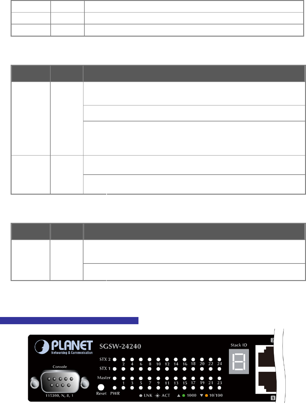
SGSW-24240 / SGSW-24240R LED indication
Figure 2-8 SGSW-24240 / SGSW-24240R LED panel