
Manual
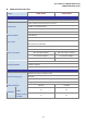
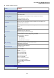
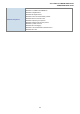

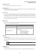

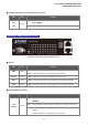


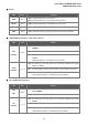
Table Of Contents
- 1. INTRODUTION
- 2. INSTALLATION
- 3. SWITCH MANAGEMENT
- 4. WEB CONFIGURATION
- 4.1 Main WEB PAGE
- 4.2 System
- 4.3 Simple Network Management Protocol
- 4.4 Port Management
- 4.5 Link Aggregation
- 4.6 VLAN
- 4.7 Rapid Spanning Tree Protocol
- 4.8 Quality of Service
- 4.9 Multicast
- 4.10 IEEE 802.1X Network Access Control
- 4.10.1 Understanding IEEE 802.1X Port-Based Authentication
- 4.10.2 802.1X System Configuration
- 4.10.3 802.1X and MAC-Based Authentication Port Configuration
- 4.10.4 802.1X Port Status
- 4.10.5 802.1X and MAC-Based Authentication Statistics
- 4.10.6 Windows Platform RADIUS Server Configuration
- 4.10.7 802.1X Client Configuration
- 4.11 Access Control Lists
- 4.12 Address Table
- 4.13 Port Security (To be Continued)
- 4.14 LLDP
- 4.15 Network Diagnastics
- 4.16 Stacking – SGSW-24040 / SGSW-24040R
- 4.17 Power over Ethernet (SGSW-24040P / SGSW-24040P4)
- 5. COMMAND LINE INTERFACE
- 6. Command Line Mode
- 6.1 System Command
- 6.2 Port Management Command
- 6.3 Link Aggregation Command
- 6.4 VLAN Configuration Command
- 6.5 Spanning Tree Protocol Command
- 6.6 Multicast Configuration Command
- 6.7 Quality of Service Command
- 6.8 802.1x Port Access Control Command
- 6.9 Access Control List Command
- 6.10 MAC Address Table Command
- 6.11 LLDP Command
- 6.12 Stack Management Command
- 6.13 Power over Ethernet Command
- 7. SWITCH OPERATION
- 8. POWER OVER ETHERNET OVERVIEW
- 9. TROUBLE SHOOTING
- APPENDEX A
- APPENDEX B : GLOSSARY
User’s Manual of WGSW-24040 Series
SGSW-24040/24240 Series
25
■ Gigabit TP interface
10/100/1000Base-T Copper, RJ-45 Twist-Pair: Up to 100 meters.
■ Gigabit SFP slots
1000Base-SX/LX mini-GBIC slot, SFP (Small Factor Pluggable) transceiver module: From 550 meters (Multi-mode fiber),
up to 10/30/50/70/120 kilometers (Single-mode fiber).
■ Console Port
The console port is a DB9, RS-232 male seria port connector. It is an interface for connecting a terminal directly. Through
the console port, it provides rich diagnostic information includes IP Address setting, factory reset, port management, link
status and system setting. Users can use the attached RS-232 cable in the package and connect to the console port on the
device. After the connection, users an run any terminal emulation program (Hyper Terminal, ProComm Plus, Telix, Winterm
and so on) to enter the statup screen of the device.
■ Reset button
At the left of front panel, the reset button is designed for reboot the Managed Switch without turn off and on the power. The
following is the summary table of Reset button functions:
Reset Button Pressed and Released Function
About 1~3 second Reboot the Managed Switch
Until the PWR LED lit off
Reset the Managed Switch to Factory Default configuration.
The Managed Switch will then reboot and load the default
settings as below:
。 Default Password: admin
。 Default IP address: 192.168.0.100
。 Subnet mask: 255.255.255.0
。 Default Gateway: 192.168.0.254
■ Stack ID
SGSW Series only
Each SGSW Managed Stackable Switch on a stack must have a unique “Stack ID”. There are 16 degrees (0~9, A~F) in the
rotary switch. The Stack ID is configured via Web or CLI management interface. Use the Stack ID to identify the localtion of
the real device.
Stack ID is not equals to the Master Priority that configured in the management interface.
■ Master LED
SGSW Series only
If master switch is fail or disconnected to the switch by stack port, the switch with least switch ID will become master.