
Manual

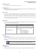


Table Of Contents
- 1. INTRODUTION
- 2. INSTALLATION
- 3. SWITCH MANAGEMENT
- 4. WEB CONFIGURATION
- 4.1 Main WEB PAGE
- 4.2 System
- 4.3 Simple Network Management Protocol
- 4.4 Port Management
- 4.5 Link Aggregation
- 4.6 VLAN
- 4.7 Rapid Spanning Tree Protocol
- 4.8 Quality of Service
- 4.9 Multicast
- 4.10 IEEE 802.1X Network Access Control
- 4.10.1 Understanding IEEE 802.1X Port-Based Authentication
- 4.10.2 802.1X System Configuration
- 4.10.3 802.1X and MAC-Based Authentication Port Configuration
- 4.10.4 802.1X Port Status
- 4.10.5 802.1X and MAC-Based Authentication Statistics
- 4.10.6 Windows Platform RADIUS Server Configuration
- 4.10.7 802.1X Client Configuration
- 4.11 Access Control Lists
- 4.12 Address Table
- 4.13 Port Security (To be Continued)
- 4.14 LLDP
- 4.15 Network Diagnastics
- 4.16 Stacking – SGSW-24040 / SGSW-24040R
- 4.17 Power over Ethernet (SGSW-24040P / SGSW-24040P4)
- 5. COMMAND LINE INTERFACE
- 6. Command Line Mode
- 6.1 System Command
- 6.2 Port Management Command
- 6.3 Link Aggregation Command
- 6.4 VLAN Configuration Command
- 6.5 Spanning Tree Protocol Command
- 6.6 Multicast Configuration Command
- 6.7 Quality of Service Command
- 6.8 802.1x Port Access Control Command
- 6.9 Access Control List Command
- 6.10 MAC Address Table Command
- 6.11 LLDP Command
- 6.12 Stack Management Command
- 6.13 Power over Ethernet Command
- 7. SWITCH OPERATION
- 8. POWER OVER ETHERNET OVERVIEW
- 9. TROUBLE SHOOTING
- APPENDEX A
- APPENDEX B : GLOSSARY
User’s Manual of WGSW-24040 Series
SGSW-24040/24240 Series
24
2. INSTALLATION
This section describes the hardware features and installation of the Managed Switch on the desktop or rack mount. For easier
management and control of the Managed Switch, familiarize yourself with its display indicators, and ports. Front panel
illustrations in this chapter display the unit LED indicators. Before connecting any network device to the Managed Switch, please
read this chapter completely.
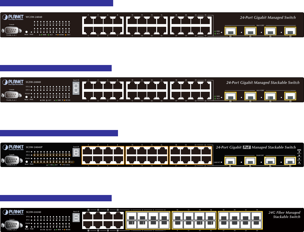
2.1 Hardware Description
2.1.1 Switch Front Panel
The unit front panel provides a simple interface monitoring the switch. Figure 2-1 to 2-4 show the front panel of the Managed
Switches.
WGSW-24040 / WGSW-24040RFront Panel
Figure 2-1 WGSW-24040 / WGSW-24040R front panel.
SGSW-24040 / SGSW-24040R Front Panel
Figure 2-2 SGSW-24040 / SGSW-24040R front panel.
SGSW-24040P / SGSW-24040P4 Front Panel
Figure 2-3 SGSW-24040P / SGSW-24040P4 front panel.
SGSW-24240 / SGSW-24240R Front Panel
Figure 2-4 SGSW-24240 / SGSW-24240R front panel.