
Manual
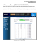
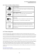


Table Of Contents
- 1. INTRODUTION
- 2. INSTALLATION
- 3. SWITCH MANAGEMENT
- 4. WEB CONFIGURATION
- 4.1 Main WEB PAGE
- 4.2 System
- 4.3 Simple Network Management Protocol
- 4.4 Port Management
- 4.5 Link Aggregation
- 4.6 VLAN
- 4.7 Rapid Spanning Tree Protocol
- 4.8 Quality of Service
- 4.9 Multicast
- 4.10 IEEE 802.1X Network Access Control
- 4.10.1 Understanding IEEE 802.1X Port-Based Authentication
- 4.10.2 802.1X System Configuration
- 4.10.3 802.1X and MAC-Based Authentication Port Configuration
- 4.10.4 802.1X Port Status
- 4.10.5 802.1X and MAC-Based Authentication Statistics
- 4.10.6 Windows Platform RADIUS Server Configuration
- 4.10.7 802.1X Client Configuration
- 4.11 Access Control Lists
- 4.12 Address Table
- 4.13 Port Security (To be Continued)
- 4.14 LLDP
- 4.15 Network Diagnastics
- 4.16 Stacking – SGSW-24040 / SGSW-24040R
- 4.17 Power over Ethernet (SGSW-24040P / SGSW-24040P4)
- 5. COMMAND LINE INTERFACE
- 6. Command Line Mode
- 6.1 System Command
- 6.2 Port Management Command
- 6.3 Link Aggregation Command
- 6.4 VLAN Configuration Command
- 6.5 Spanning Tree Protocol Command
- 6.6 Multicast Configuration Command
- 6.7 Quality of Service Command
- 6.8 802.1x Port Access Control Command
- 6.9 Access Control List Command
- 6.10 MAC Address Table Command
- 6.11 LLDP Command
- 6.12 Stack Management Command
- 6.13 Power over Ethernet Command
- 7. SWITCH OPERATION
- 8. POWER OVER ETHERNET OVERVIEW
- 9. TROUBLE SHOOTING
- APPENDEX A
- APPENDEX B : GLOSSARY

User’s Manual of WGSW-24040 Series
SGSW-24040/24240 Series
218
• Total Power Reserved
Shows how much the total power be reserved for all PDs.
• PoE Temperature Unit 1
Display the current operating temperature of PoE chip unit 1.
The unit 1 is in charge of PoE Port-1~Port-12
• PoE Temperature Unit 2
Display the current operating temperature of PoE chip unit 2.
The unit 1 is in charge of PoE Port-13~Port-24
• Local Port
This is the logical port number for this row.
•
Display the class of the PD attached to the port, as established by the classification
process.
Class 0 is the default for PDs. The PD is classified based on power. The
classification of the PD is the maximum power that the PD will draw across all input
voltages and operational modes. A PD shall return Class 0 to 3 in accordance with
the maximum power draw as specified by Table 4-17-1.
• Power Reserved
The Power Reserved shows how much the power the PD has reserved.
• Power Used
The Power Used shows how much power the PD currently is using.
• Current Used
The Power Used shows how much current the PD currently is using.
• Priority
The Priority shows the port's priority configured by the user.
• Port Status
The Port Status shows the port's status.
• Total
Show the total watts usage of all PDs.