
Manual
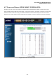
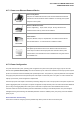


Table Of Contents
- 1. INTRODUTION
- 2. INSTALLATION
- 3. SWITCH MANAGEMENT
- 4. WEB CONFIGURATION
- 4.1 Main WEB PAGE
- 4.2 System
- 4.3 Simple Network Management Protocol
- 4.4 Port Management
- 4.5 Link Aggregation
- 4.6 VLAN
- 4.7 Rapid Spanning Tree Protocol
- 4.8 Quality of Service
- 4.9 Multicast
- 4.10 IEEE 802.1X Network Access Control
- 4.10.1 Understanding IEEE 802.1X Port-Based Authentication
- 4.10.2 802.1X System Configuration
- 4.10.3 802.1X and MAC-Based Authentication Port Configuration
- 4.10.4 802.1X Port Status
- 4.10.5 802.1X and MAC-Based Authentication Statistics
- 4.10.6 Windows Platform RADIUS Server Configuration
- 4.10.7 802.1X Client Configuration
- 4.11 Access Control Lists
- 4.12 Address Table
- 4.13 Port Security (To be Continued)
- 4.14 LLDP
- 4.15 Network Diagnastics
- 4.16 Stacking – SGSW-24040 / SGSW-24040R
- 4.17 Power over Ethernet (SGSW-24040P / SGSW-24040P4)
- 5. COMMAND LINE INTERFACE
- 6. Command Line Mode
- 6.1 System Command
- 6.2 Port Management Command
- 6.3 Link Aggregation Command
- 6.4 VLAN Configuration Command
- 6.5 Spanning Tree Protocol Command
- 6.6 Multicast Configuration Command
- 6.7 Quality of Service Command
- 6.8 802.1x Port Access Control Command
- 6.9 Access Control List Command
- 6.10 MAC Address Table Command
- 6.11 LLDP Command
- 6.12 Stack Management Command
- 6.13 Power over Ethernet Command
- 7. SWITCH OPERATION
- 8. POWER OVER ETHERNET OVERVIEW
- 9. TROUBLE SHOOTING
- APPENDEX A
- APPENDEX B : GLOSSARY

User’s Manual of WGSW-24040 Series
SGSW-24040/24240 Series
212
4.17.1 Power over Ethernet Powered Device
3~5 watts
Voice over IP phones
Enterprise can install POE VoIP Phone, ATA and other Ethernet/non-Ethernet
end-devices to the central where UPS is installed for un-interrupt power system
and power control system.
6~12 watts
Wireless LAN Access Points
Museum, Sightseeing, Airport, Hotel, Campus, Factory, Warehouse can
install the Access Point any where with no hesitation
10~12 watts
IP Surveillance
Enterprise, Museum, Campus, Hospital, Bank, can install IP Camera without
limits of install location – no need electrician to install AC sockets.
3~12 watts
PoE Splitter
PoE Splitter split the PoE 48V DC over the Ethernet cable into 5/9/12V DC
power output. It frees the device deployment from restrictions due to power
outlet locations, which eliminate the costs for additional AC wiring and reduces
the installation time.
4.17.2 Power Configuration
In a power over Ethernet system, operating power is applied from a power source (PSU-power supply unit) over the LAN
infrastructure to powered devices (PDs), which are connected to ports. Under some conditions, the total output power required
by PDs can exceed the maximum available power provided by the PSU. The system may a prior be planed with a PSU capable
of supplying less power than the total potential power consumption of all the PoE ports in the system. In order to maintain the
majority of ports active, power management is implemented.
The PSU input power consumption is monitored by measuring voltage and current .The input power consumption is equal to the
system’s aggregated power consumption .The power management concept allows all ports to be active and activates additional
ports, as long as the aggregated power of the system is lower than the power level at which additional PDs cannot be
connected .When this value is exceeded, ports will be deactivated, according to user-defined priorities. The power budget is
managed according to the following user-definable parameters: maximum available power, ports priority, maximum allowable
power per port.
Reserved Power determined by
There are five modes for configuring how the ports/PDs may reserve power and when to shut down ports.