
Manual

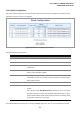
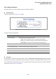

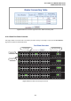

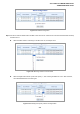

Table Of Contents
- 1. INTRODUTION
- 2. INSTALLATION
- 3. SWITCH MANAGEMENT
- 4. WEB CONFIGURATION
- 4.1 Main WEB PAGE
- 4.2 System
- 4.3 Simple Network Management Protocol
- 4.4 Port Management
- 4.5 Link Aggregation
- 4.6 VLAN
- 4.7 Rapid Spanning Tree Protocol
- 4.8 Quality of Service
- 4.9 Multicast
- 4.10 IEEE 802.1X Network Access Control
- 4.10.1 Understanding IEEE 802.1X Port-Based Authentication
- 4.10.2 802.1X System Configuration
- 4.10.3 802.1X and MAC-Based Authentication Port Configuration
- 4.10.4 802.1X Port Status
- 4.10.5 802.1X and MAC-Based Authentication Statistics
- 4.10.6 Windows Platform RADIUS Server Configuration
- 4.10.7 802.1X Client Configuration
- 4.11 Access Control Lists
- 4.12 Address Table
- 4.13 Port Security (To be Continued)
- 4.14 LLDP
- 4.15 Network Diagnastics
- 4.16 Stacking – SGSW-24040 / SGSW-24040R
- 4.17 Power over Ethernet (SGSW-24040P / SGSW-24040P4)
- 5. COMMAND LINE INTERFACE
- 6. Command Line Mode
- 6.1 System Command
- 6.2 Port Management Command
- 6.3 Link Aggregation Command
- 6.4 VLAN Configuration Command
- 6.5 Spanning Tree Protocol Command
- 6.6 Multicast Configuration Command
- 6.7 Quality of Service Command
- 6.8 802.1x Port Access Control Command
- 6.9 Access Control List Command
- 6.10 MAC Address Table Command
- 6.11 LLDP Command
- 6.12 Stack Management Command
- 6.13 Power over Ethernet Command
- 7. SWITCH OPERATION
- 8. POWER OVER ETHERNET OVERVIEW
- 9. TROUBLE SHOOTING
- APPENDEX A
- APPENDEX B : GLOSSARY
User’s Manual of WGSW-24040 Series
SGSW-24040/24240 Series
208
4.16.5 Stack Example
Stacking function is convenient for administrator to manage multiple switches by single IP. Basically, you got to have min. 2 units.
The SGSW Switch supports auto stack configuration. Once the stack cable is connect to the stack port of each SGSW switch
and power on them, the stack is builded automatically and the Switch ID is automatically assigned to the switch. It is also easy
to add or delete stackable switch to the stack without service interruption. The key point of the Stack management are:
Identify the MASTER SWITCH
Assign / re-assing Switch ID for each management purpose
Step 1: linking the switches by CB-STX50 stack cable.
Step 2: Check the Master LED of each SGSW switch to find out the Master Switch that is elected automatically by the stack
operation.
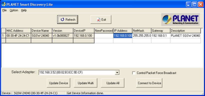
Step 3: Use the Web browser such as IE 6.0 to login the Master Switch, the default IP address is 192.168.0.100. Or you can use
the PLANET Smart Discovery Utility to find out the IP address of the stack group.
Figure 4-16-11 Use PLANET Smart Discovery Utility to display the IP address of stack master
Step 4: Choose “Stack \ Stack Configuration” from menu tree. You can see the Stack had established automaticatlly. As the
below screen appears:
1. The Switch ID is automatically assigned to the switches
2. All switches with same Priority value “3”.
3. The one can’t be delete is the Stack master.