
Manual

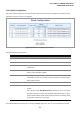
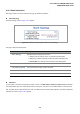


Table Of Contents
- 1. INTRODUTION
- 2. INSTALLATION
- 3. SWITCH MANAGEMENT
- 4. WEB CONFIGURATION
- 4.1 Main WEB PAGE
- 4.2 System
- 4.3 Simple Network Management Protocol
- 4.4 Port Management
- 4.5 Link Aggregation
- 4.6 VLAN
- 4.7 Rapid Spanning Tree Protocol
- 4.8 Quality of Service
- 4.9 Multicast
- 4.10 IEEE 802.1X Network Access Control
- 4.10.1 Understanding IEEE 802.1X Port-Based Authentication
- 4.10.2 802.1X System Configuration
- 4.10.3 802.1X and MAC-Based Authentication Port Configuration
- 4.10.4 802.1X Port Status
- 4.10.5 802.1X and MAC-Based Authentication Statistics
- 4.10.6 Windows Platform RADIUS Server Configuration
- 4.10.7 802.1X Client Configuration
- 4.11 Access Control Lists
- 4.12 Address Table
- 4.13 Port Security (To be Continued)
- 4.14 LLDP
- 4.15 Network Diagnastics
- 4.16 Stacking – SGSW-24040 / SGSW-24040R
- 4.17 Power over Ethernet (SGSW-24040P / SGSW-24040P4)
- 5. COMMAND LINE INTERFACE
- 6. Command Line Mode
- 6.1 System Command
- 6.2 Port Management Command
- 6.3 Link Aggregation Command
- 6.4 VLAN Configuration Command
- 6.5 Spanning Tree Protocol Command
- 6.6 Multicast Configuration Command
- 6.7 Quality of Service Command
- 6.8 802.1x Port Access Control Command
- 6.9 Access Control List Command
- 6.10 MAC Address Table Command
- 6.11 LLDP Command
- 6.12 Stack Management Command
- 6.13 Power over Ethernet Command
- 7. SWITCH OPERATION
- 8. POWER OVER ETHERNET OVERVIEW
- 9. TROUBLE SHOOTING
- APPENDEX A
- APPENDEX B : GLOSSARY
User’s Manual of WGSW-24040 Series
SGSW-24040/24240 Series
205
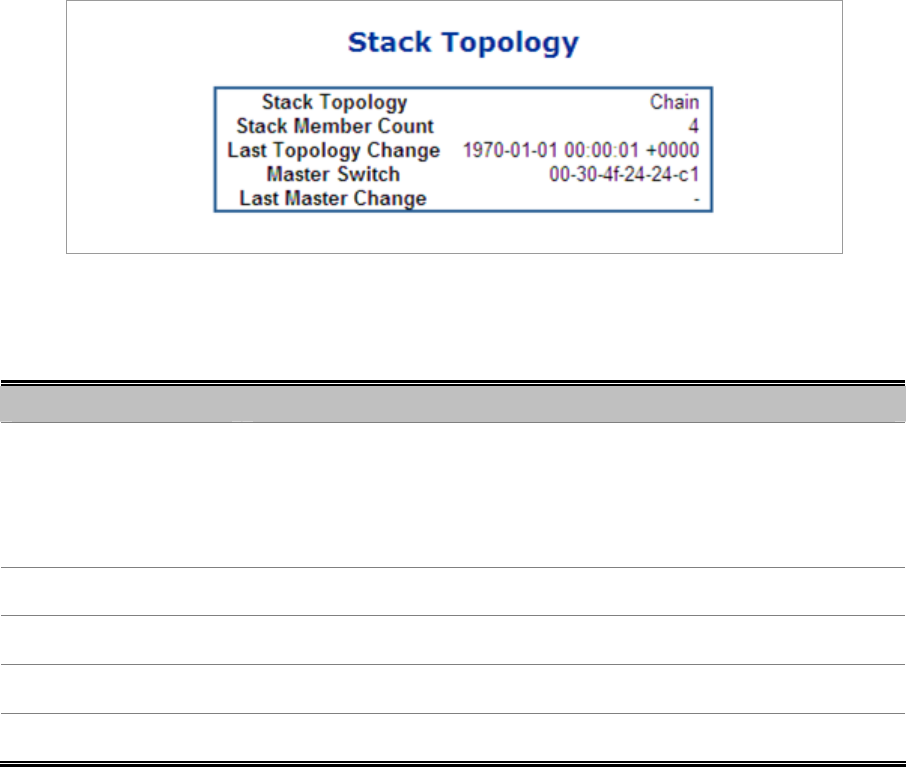
4.16.3 Stack Information
This page provides an overview of the stack topology, as detected by SPROUT.
Stack Topology
The Stack Topology screen in Figure 4-16-7 appears.
Figure 4-16-7 Stack Information page screenshot - Stack Topology
The page includes the following fields:
Object Description
• Stack Topology
Specifies the type of topology for the stack:
• Chain: A chain of switches, that is, no redundant forwarding paths.
• Ring: A ring of switches, thereby providing redundant forwarding paths.
• Back-to-Back: Two switches interconnected on both stacking ports.
• Stack Member Count
The number of switches in the stack.
• Last Topology Change
The time of the last topology change in the stack.
• Master Switch
The MAC address of the current stack master switch.
• Last Master Change
The time of the last master change in the stack.
Stack List
For each switch in the stack, the following information is shown: The MAC address, Switch ID, product name and version,
and master election state. The master election state is normally "No". Only when a forced master election is enforced by the
user, the master election state takes the value "Yes". For details about the master election algorithm, see Stack Configuration.
The Stack List screen in Figure 4-16-8 appears.