
Manual


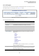
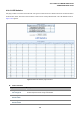


Table Of Contents
- 1. INTRODUTION
- 2. INSTALLATION
- 3. SWITCH MANAGEMENT
- 4. WEB CONFIGURATION
- 4.1 Main WEB PAGE
- 4.2 System
- 4.3 Simple Network Management Protocol
- 4.4 Port Management
- 4.5 Link Aggregation
- 4.6 VLAN
- 4.7 Rapid Spanning Tree Protocol
- 4.8 Quality of Service
- 4.9 Multicast
- 4.10 IEEE 802.1X Network Access Control
- 4.10.1 Understanding IEEE 802.1X Port-Based Authentication
- 4.10.2 802.1X System Configuration
- 4.10.3 802.1X and MAC-Based Authentication Port Configuration
- 4.10.4 802.1X Port Status
- 4.10.5 802.1X and MAC-Based Authentication Statistics
- 4.10.6 Windows Platform RADIUS Server Configuration
- 4.10.7 802.1X Client Configuration
- 4.11 Access Control Lists
- 4.12 Address Table
- 4.13 Port Security (To be Continued)
- 4.14 LLDP
- 4.15 Network Diagnastics
- 4.16 Stacking – SGSW-24040 / SGSW-24040R
- 4.17 Power over Ethernet (SGSW-24040P / SGSW-24040P4)
- 5. COMMAND LINE INTERFACE
- 6. Command Line Mode
- 6.1 System Command
- 6.2 Port Management Command
- 6.3 Link Aggregation Command
- 6.4 VLAN Configuration Command
- 6.5 Spanning Tree Protocol Command
- 6.6 Multicast Configuration Command
- 6.7 Quality of Service Command
- 6.8 802.1x Port Access Control Command
- 6.9 Access Control List Command
- 6.10 MAC Address Table Command
- 6.11 LLDP Command
- 6.12 Stack Management Command
- 6.13 Power over Ethernet Command
- 7. SWITCH OPERATION
- 8. POWER OVER ETHERNET OVERVIEW
- 9. TROUBLE SHOOTING
- APPENDEX A
- APPENDEX B : GLOSSARY
User’s Manual of WGSW-24040 Series
SGSW-24040/24240 Series
197
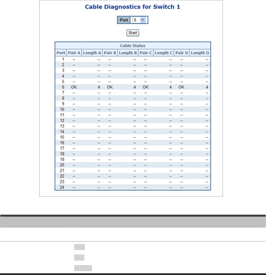
4.15 Network Diagnastics
4.15.1 Cable Diagnostics
This page is used for running the Cable Diagnostics.
Press to run the diagnostics. This will take approximately 5 seconds. If all ports are selected, this can take approximately 15
seconds. When completed, the page refreshes automatically, and you can view the cable diagnostics results in the cable status
table. Note that Cable Diagnostics is only accurate for cables of length 7 - 140 meters.
10 and 100 Mbps ports will be linked down while running cable diagnostic. Therefore, running cable diagnastic on a 10 or 100
Mbps management port will cause the switch to stop responding until VeriPHY is complete. The ports belong to the currently
selected stack unit, as reflected by the page header.
Figure 4-15-1 Cable Diagnostics page screenshot
Object Description
• Port
The port where you are requesting Cable Diagnostics.
• Cable Status
Port: Port number.
Pair: The status of the cable pair.
Length: The length (in meters) of the cable pair.