
Manual
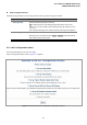


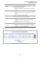


Table Of Contents
- 1. INTRODUTION
- 2. INSTALLATION
- 3. SWITCH MANAGEMENT
- 4. WEB CONFIGURATION
- 4.1 Main WEB PAGE
- 4.2 System
- 4.3 Simple Network Management Protocol
- 4.4 Port Management
- 4.5 Link Aggregation
- 4.6 VLAN
- 4.7 Rapid Spanning Tree Protocol
- 4.8 Quality of Service
- 4.9 Multicast
- 4.10 IEEE 802.1X Network Access Control
- 4.10.1 Understanding IEEE 802.1X Port-Based Authentication
- 4.10.2 802.1X System Configuration
- 4.10.3 802.1X and MAC-Based Authentication Port Configuration
- 4.10.4 802.1X Port Status
- 4.10.5 802.1X and MAC-Based Authentication Statistics
- 4.10.6 Windows Platform RADIUS Server Configuration
- 4.10.7 802.1X Client Configuration
- 4.11 Access Control Lists
- 4.12 Address Table
- 4.13 Port Security (To be Continued)
- 4.14 LLDP
- 4.15 Network Diagnastics
- 4.16 Stacking – SGSW-24040 / SGSW-24040R
- 4.17 Power over Ethernet (SGSW-24040P / SGSW-24040P4)
- 5. COMMAND LINE INTERFACE
- 6. Command Line Mode
- 6.1 System Command
- 6.2 Port Management Command
- 6.3 Link Aggregation Command
- 6.4 VLAN Configuration Command
- 6.5 Spanning Tree Protocol Command
- 6.6 Multicast Configuration Command
- 6.7 Quality of Service Command
- 6.8 802.1x Port Access Control Command
- 6.9 Access Control List Command
- 6.10 MAC Address Table Command
- 6.11 LLDP Command
- 6.12 Stack Management Command
- 6.13 Power over Ethernet Command
- 7. SWITCH OPERATION
- 8. POWER OVER ETHERNET OVERVIEW
- 9. TROUBLE SHOOTING
- APPENDEX A
- APPENDEX B : GLOSSARY
User’s Manual of WGSW-24040 Series
SGSW-24040/24240 Series
180
The page includes the following fields:
Object Description
• Ingress Port
Select the ingress port to which this ACE applies.
• Any: The ACE applies to any port.
• Port n: The ACE applies to this port number, where n is the number of the
switch port.
• Policy n: The ACE applies to this policy number, where n can range from 1
through 8.
• Switch
Select the switch to which this ACE applies.
• Any: The ACE applies to any port.
• Switch n: The ACE applies to this switch number, where n is the number of
the switch.
• Action
Specify the action to take with a frame that hits this ACE.
• Permit: The frame that hits this ACE is granted permission for the ACE
operation.
• Deny: The frame that hits this ACE is dropped.
• Rate Limiter
Specify the rate limiter in number of base units. The allowed range is 1 to 15.
Disabled indicates that the rate limiter operation is disabled.
• Logging
Specify the logging operation of the ACE. The allowed values are:
• Enabled: Frames matching the ACE are stored in the System Log.
• Disabled: Frames matching the ACE are not logged.
• Shutdown
Specify the port shut down operation of the ACE. The allowed values are:
• Enabled: If a frame matches the ACE, the ingress port will be disabled.
• Disabled: Port shut down is disabled for the ACE.
Please note that the System Log memory size and logging rate is limited.
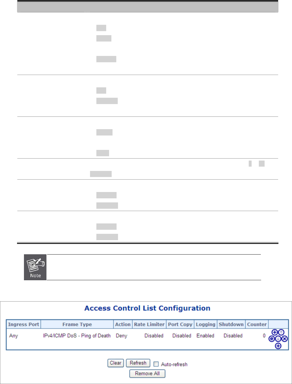
The ACL configuration wizard is finished, and the new configuration is ready for use.
Figure 4-11-12