
Manual

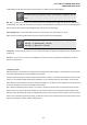
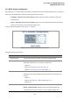

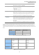


Table Of Contents
- 1. INTRODUTION
- 2. INSTALLATION
- 3. SWITCH MANAGEMENT
- 4. WEB CONFIGURATION
- 4.1 Main WEB PAGE
- 4.2 System
- 4.3 Simple Network Management Protocol
- 4.4 Port Management
- 4.5 Link Aggregation
- 4.6 VLAN
- 4.7 Rapid Spanning Tree Protocol
- 4.8 Quality of Service
- 4.9 Multicast
- 4.10 IEEE 802.1X Network Access Control
- 4.10.1 Understanding IEEE 802.1X Port-Based Authentication
- 4.10.2 802.1X System Configuration
- 4.10.3 802.1X and MAC-Based Authentication Port Configuration
- 4.10.4 802.1X Port Status
- 4.10.5 802.1X and MAC-Based Authentication Statistics
- 4.10.6 Windows Platform RADIUS Server Configuration
- 4.10.7 802.1X Client Configuration
- 4.11 Access Control Lists
- 4.12 Address Table
- 4.13 Port Security (To be Continued)
- 4.14 LLDP
- 4.15 Network Diagnastics
- 4.16 Stacking – SGSW-24040 / SGSW-24040R
- 4.17 Power over Ethernet (SGSW-24040P / SGSW-24040P4)
- 5. COMMAND LINE INTERFACE
- 6. Command Line Mode
- 6.1 System Command
- 6.2 Port Management Command
- 6.3 Link Aggregation Command
- 6.4 VLAN Configuration Command
- 6.5 Spanning Tree Protocol Command
- 6.6 Multicast Configuration Command
- 6.7 Quality of Service Command
- 6.8 802.1x Port Access Control Command
- 6.9 Access Control List Command
- 6.10 MAC Address Table Command
- 6.11 LLDP Command
- 6.12 Stack Management Command
- 6.13 Power over Ethernet Command
- 7. SWITCH OPERATION
- 8. POWER OVER ETHERNET OVERVIEW
- 9. TROUBLE SHOOTING
- APPENDEX A
- APPENDEX B : GLOSSARY
User’s Manual of WGSW-24040 Series
SGSW-24040/24240 Series
115
Compatible – Classis STP (802.1d): Provides a single path between end
stations, avoiding and eliminating loops.
The Gigabit Ethernet Switch implement the Rapid Spanning Protocol as the default spanning tree
protocol. While select “Compatibles” mode, the system use the RSTP (802.1w) to compatible and
co work with another STP (802.1d)’s BPDU control packets.
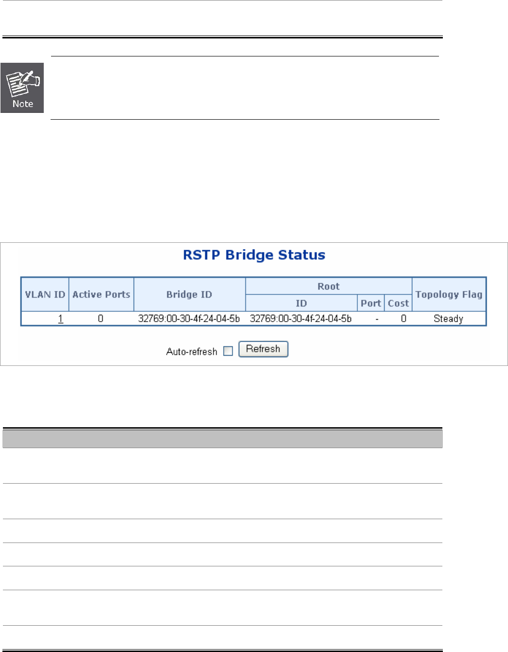
4.7.3 RSTP Bridge Status
This page provides a status overview for all RSTP bridge instances.
The displayed table contains a row for each RSTP bridge instance, where the column displays the following information:
The RSTP Bridge Status screen in Figure 4-7-8 appears.
Figure 4-7-8 RSTP Bridge Status page screenshot
The page includes the following fields:
Object Description
• VLAN ID
The VLAN ID associated with this Bridge instance. This is also a link to the RSTP
Detailed Bridge Status.
• Active Ports
The number switch ports active in the RSTP bridge instance (aggregated ports
count only as one).
• Bridge ID
The Bridge ID of this Bridge instance.
• Root ID
The Bridge ID of the currently elected root bridge.
• Root Port
The switch port currently assigned the root port role.
• Root Cost
Root Path Cost. For the Root Bridge this is zero. For all other Bridges, it is the
sum of the Port Path Costs on the least cost path to the Root Bridge.
• Topology Flag
The current state of the Topology Change Flag for this Bridge instance.