
Manual

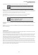
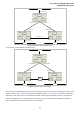


Table Of Contents
- 1. INTRODUTION
- 2. INSTALLATION
- 3. SWITCH MANAGEMENT
- 4. WEB CONFIGURATION
- 4.1 Main WEB PAGE
- 4.2 System
- 4.3 Simple Network Management Protocol
- 4.4 Port Management
- 4.5 Link Aggregation
- 4.6 VLAN
- 4.7 Rapid Spanning Tree Protocol
- 4.8 Quality of Service
- 4.9 Multicast
- 4.10 IEEE 802.1X Network Access Control
- 4.10.1 Understanding IEEE 802.1X Port-Based Authentication
- 4.10.2 802.1X System Configuration
- 4.10.3 802.1X and MAC-Based Authentication Port Configuration
- 4.10.4 802.1X Port Status
- 4.10.5 802.1X and MAC-Based Authentication Statistics
- 4.10.6 Windows Platform RADIUS Server Configuration
- 4.10.7 802.1X Client Configuration
- 4.11 Access Control Lists
- 4.12 Address Table
- 4.13 Port Security (To be Continued)
- 4.14 LLDP
- 4.15 Network Diagnastics
- 4.16 Stacking – SGSW-24040 / SGSW-24040R
- 4.17 Power over Ethernet (SGSW-24040P / SGSW-24040P4)
- 5. COMMAND LINE INTERFACE
- 6. Command Line Mode
- 6.1 System Command
- 6.2 Port Management Command
- 6.3 Link Aggregation Command
- 6.4 VLAN Configuration Command
- 6.5 Spanning Tree Protocol Command
- 6.6 Multicast Configuration Command
- 6.7 Quality of Service Command
- 6.8 802.1x Port Access Control Command
- 6.9 Access Control List Command
- 6.10 MAC Address Table Command
- 6.11 LLDP Command
- 6.12 Stack Management Command
- 6.13 Power over Ethernet Command
- 7. SWITCH OPERATION
- 8. POWER OVER ETHERNET OVERVIEW
- 9. TROUBLE SHOOTING
- APPENDEX A
- APPENDEX B : GLOSSARY
User’s Manual of WGSW-24040 Series
SGSW-24040/24240 Series
112
the Root Bridge, the set Hello Time will be used if and when your Switch becomes the Root Bridge.
The Hello Time cannot be longer than the Max. Age. Otherwise, a configuration error will
occur.
Max. Age – The Max Age can be from 6 to 40 seconds. At the end of the Max Age, if a BPDU has still not been received from
the Root Bridge, your Switch will start sending its own BPDU to all other Switches for permission to become the Root Bridge. If it
turns out that your Switch has the lowest Bridge Identifier, it will become the Root Bridge.
Forward Delay Timer – The Forward Delay can be from 4 to 30 seconds. This is the time any port on the
Switch spends in the listening state while moving from the blocking state to the forwarding state.
Observe the following formulas when setting the above parameters:
Max. Age _ 2 x (Forward Delay - 1 second)
Max. Age _ 2 x (Hello Time + 1 second)
Port Priority – A Port Priority can be from 0 to 240. The lower the number, the greater the probability the port will be chosen as
the Root Port.
Port Cost – A Port Cost can be set from 0 to 200000000. The lower the number, the greater the probability the port will be
chosen to forward packets.
3. Illustration of STP
A simple illustration of three switches connected in a loop is depicted in the below diagram. In this example, you can anticipate
some major network problems if the STP assistance is not applied.
If switch A broadcasts a packet to switch B, switch B will broadcast it to switch C, and switch C will broadcast it to back to switch
A and so on. The broadcast packet will be passed indefinitely in a loop, potentially causing a network failure. In this example,
STP breaks the loop by blocking the connection between switch B and C. The decision to block a particular connection is based
on the STP calculation of the most current Bridge and Port settings.
Now, if switch A broadcasts a packet to switch C, then switch C will drop the packet at port 2 and the broadcast will end there.
Setting-up STP using values other than the defaults, can be complex. Therefore, you are advised to keep the default factory
settings and STP will automatically assign root bridges/ports and block loop connections. Influencing STP to choose a particular
switch as the root bridge using the Priority setting, or influencing STP to choose a particular port to block using the Port Priority
and Port Cost settings is, however, relatively straight forward.