
Manual
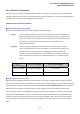
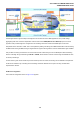


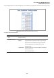
Table Of Contents
- 1. INTRODUTION
- 2. INSTALLATION
- 3. SWITCH MANAGEMENT
- 4. WEB CONFIGURATION
- 4.1 Main WEB PAGE
- 4.2 System
- 4.3 Simple Network Management Protocol
- 4.4 Port Management
- 4.5 Link Aggregation
- 4.6 VLAN
- 4.7 Rapid Spanning Tree Protocol
- 4.8 Quality of Service
- 4.9 Multicast
- 4.10 IEEE 802.1X Network Access Control
- 4.10.1 Understanding IEEE 802.1X Port-Based Authentication
- 4.10.2 802.1X System Configuration
- 4.10.3 802.1X and MAC-Based Authentication Port Configuration
- 4.10.4 802.1X Port Status
- 4.10.5 802.1X and MAC-Based Authentication Statistics
- 4.10.6 Windows Platform RADIUS Server Configuration
- 4.10.7 802.1X Client Configuration
- 4.11 Access Control Lists
- 4.12 Address Table
- 4.13 Port Security (To be Continued)
- 4.14 LLDP
- 4.15 Network Diagnastics
- 4.16 Stacking – SGSW-24040 / SGSW-24040R
- 4.17 Power over Ethernet (SGSW-24040P / SGSW-24040P4)
- 5. COMMAND LINE INTERFACE
- 6. Command Line Mode
- 6.1 System Command
- 6.2 Port Management Command
- 6.3 Link Aggregation Command
- 6.4 VLAN Configuration Command
- 6.5 Spanning Tree Protocol Command
- 6.6 Multicast Configuration Command
- 6.7 Quality of Service Command
- 6.8 802.1x Port Access Control Command
- 6.9 Access Control List Command
- 6.10 MAC Address Table Command
- 6.11 LLDP Command
- 6.12 Stack Management Command
- 6.13 Power over Ethernet Command
- 7. SWITCH OPERATION
- 8. POWER OVER ETHERNET OVERVIEW
- 9. TROUBLE SHOOTING
- APPENDEX A
- APPENDEX B : GLOSSARY
User’s Manual of WGSW-24040 Series
SGSW-24040/24240 Series
105
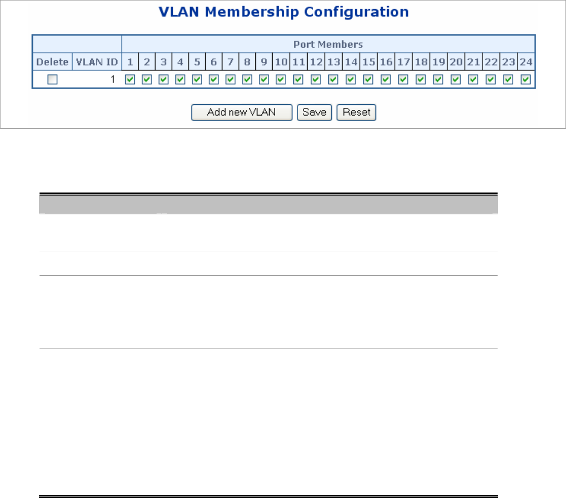
4.6.5 VLAN Membership Configuration
Adding Static Members to VLANs (VLAN Index)
Use the VLAN Static Table to configure port members for the selected VLAN index. Assign ports as tagged if they are connected
to 802.1Q VLAN compliant devices, or untagged they are not connected to any VLAN-aware devices.
The VLAN membership configuration for the selected stack switch unit switch can be monitored and modified here. Up to 64
VLANs are supported. This page allows for adding and deleting VLANs as well as adding and deleting port members of each
VLAN. The VLAN Membership Configuration screen in Figure 4-6-3 appears.
Figure 4-6-3 VLAN Membership Configuration page screenshot
The page includes the following fields:
Object Description
• Delete
To delete a VLAN entry, check this box.
The entry will be deleted on all stack switch units during the next Save.
• VLAN ID
Indicates the ID of this particular VLAN.
• Port Members
A row of check boxes for each port is displayed for each VLAN ID. To include a
port in a VLAN, check the box. To remove or exclude the port from the VLAN,
make sure the box is unchecked. By default, no ports are members, and all
boxes are unchecked.
• Adding a New VLAN
Click to add a new VLAN ID. An empty row is added to the table, and the VLAN
can be configured as needed. Legal values for a VLAN ID are 1 through 4095.
The VLAN is enabled on the selected stack switch unit when you click on "Save".
The VLAN is thereafter present on the other stack switch units, but with no port
members.
A VLAN without any port members on any stack unit will be deleted when you
click "Save".
The button can be used to undo the addition of new VLANs.