0/100/1000Mbps Intelligent Stackable Switch SGSW-2402 User’s Manual
Trademarks Copyright PLANET Technology Corp. 2002. Contents subject to revision without prior notice. PLANET is a registered trademark of PLANET Technology Corp. All other trademarks belong to their respective owners. Disclaimer PLANET Technology does not warrant that the hardware will work properly in all environments and applications, and makes no warranty and representation, either implied or expressed, with respect to the quality, performance, merchantability, or fitness for a particular purpose.
TABLE OF CONTENTS 1. INTRODUCTION........................................................................................................................................ 1 1.1 CHECKLIST ............................................................................................................................................. 1 1.2 ABOUT THE SWITCH ................................................................................................................................ 1 1.3 FEATURES .................
.2.3. sys show IP ................................................................................................................................. 44 4.2.4. sys show Ethernet address........................................................................................................ 45 4.2.5. sys set ip .................................................... 45 4.2.6. sys set name "string"..........................................................................
1. INTRODUCTION 1.1 Checklist Check the contents of your package for following parts: SGSW-2402. User's manual CD. Power cord. 19” rack mounting kit. RS-232 cable. Quick Installation Guide. If any of these pieces are missing or damaged, please contact your dealer immediately, if possible, retain the carton including the original packing material, and use them against to repack the product in case there is a need to return it to us for repair. 1.
-- LED indicators for simple diagnostics and management -- Internal power supply -- Auto MDI/ MDI-X on each port -- Network management configuration: − Web-based management − Console and Telnet Configuration − SNMP network management − IEEE 802.1Q Tagging VLAN (32 VLAN Group) − Port Trunking supported − IEEE 802.1D Spanning Tree Protocol (STP) − IGMP and Sniffer (Port Mirroring) supported − Port Priority - 802.
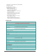
VLAN 802.1Q VLAN, up to 32 VLANs supported QoS IEEE 802.1p QoS support with 2 priority queue using WFQ (Weighted Fair Queueing) IGMP Multicast Filtering Passive snooping on IGMP Query/Report messages Port trunking Up to 4 ports can be combined into a fat pipe Port Mirroring 1 mirroring port to monitor several mirrored ports Standards Conformance Regulation Compliance FCC Part 15 Class A, CE Standards Compliance IEEE 802.3 (Ethernet) IEEE 802.3u (Fast Ethernet), IEEE 802.
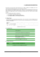
2. HARDWARE DESCRIPTION This product series provide three different running speed – 10Mbps, 100Mbps, and 1000Mbps in the same switch and automatically distinguish the speed of incoming connection. This section describes the hardware features of these Switches. For easier management and control of the switch, familiarize yourself with its display indicators, and ports. Front panel illustrations in this chapter display the unit LED indicators.
2.2 Rear Panel The rear panel of the Switch indicates an AC inlet power socket which accepts input power from 100 to 240VAC, 50-60Hz. SGSW-2402 Switch rear panel Power Notice: 1. The device is a power-required device, it means, it will not work till it is powered. If your networks should active all the time, please consider using UPS (Uninterrupted Power Supply) for your device. It will prevent you from network data loss or network downtime. 2.
♦ Baud : 38400 ♦ Parity : None ♦ Data bits : 8 ♦ Stop bits : 1 ♦ Flow Control: none Once the terminal has connected to the device, power on the device. The terminal will display that it is loading the firmware. Then, the screen as below will show up: Press “Enter” and input the password. The default password is “admin”. 2.5 IP Configuration Once log on to the console, the “Command>” prompt will be shown. You can type “help” for all available commands.
To setup the IP address, please use “sys set ip” command in the following format: sys set ip For example, to configure the switch with the following IP settings: IP Address: 192.168.0.2 Subnet Mask: 255.255.255.0 Default Gateway: 192.168.0.254 Press input the following command and press button: sys set ip 192.168.0.2 255.255.255.0 192.168.0.254 If the IP is successful configured, the switch will automatically restart as the following window.
3.WEB-BASED MANAGEMENT 3.1 Configuration As well as the menu-driven system configuration program, the agent module provides an embedded HTTP Web agent. This agent can be accessed by any computer on the network using a standard Web browser (Internet Explorer 5.0 or above, or Netscape Navigator 4.5 or above). Using the Web browser management interface you can configure a switch and view statistics to monitor network activity.
3.2 Web Pages To access the Web-browser interface you must first enter the password. The default password is "admin" You will see the following screen comes out on the Web browser program: Figure 3-1 : Password Screen After the password is entered you will see the main menu screen. Figure 3-2: The start up screen of SGSW-2402 Web Page 3.3 Port Config This section allows you to have an easy access in configuring the ports of the management Switch. Notice that the “Link state” option indicates “Up”.
Figure 3-3 The Port Config screen Choose Port You can choose a port either by clicking on the picture or by selecting it at the “Choose Port” field. Speed/ Duplex Speed/ Duplex is to select the operation mode of chosen port.
is recommended to locate the link your PC used before disable the port state. Flow Control This feature enables or disables the Flow Control function of the port. Flow control can eliminate frame loss by "blocking" traffic from end stations or segments connected directly to the switch when its buffers fill. IEEE 802.3x flow control is used for full duplex. Note that flow control should not be used if a port is connected to a hub. 3.
3.5 Trunk config Port Trunking is the ability to group together several switch ports to increase the bandwidth between the management switch and other switch. This is an inexpensive method to increase throughput between switches (or to servers). We define the Port Trunking as the ability to group a set of ports into a single logical link. The port trunk acts as single link between switches. It doesn’t create a loop even though it is physically connected as such.
3.6 Advanced Configuration The available options in “Advanced menu” are: STP Config The Spanning Tree Setup Screen IGMP Config The IGMP Setup Screen Stack Config The Stack Setup Screen SNMP Config The SNMP Setup Screen RMON Statistics Show RMON statistics information Port Security The Port Security Setup Screen MirrorPort Config The Mirror Port Setup Screen Aging Control The Aging Control Setup Screen Address Search The Address Search Setup Screen 3.
3.7.2 STP Bridge This page lets you to have a clearer view in Spanning Tree parameters for whole switch. Figure 3-6 The Spanning Tree Screen Description of Parameters STP State When STP is enabled, it will dynamically detect network looping owing to mis-configuration of the network topology. The redundant connectors will be disabled to avoid looping of packets. Looping would often result in flooding of broadcast packets, halting the normal traffic.
Step 4: Click “Apply” button and save it if everything is OK. NOTE The screen is divided into two sections. Current Spanning Tree Root section displays the read-only Spanning Tree settings for the current root switch and the parameters this switch is to use when it becomes the root switch. 3.8 IGMP Internet Group Management Protocol (IGMP) is an Internet protocol that provides a way for an Internet computer to report its multicast group membership to adjacent routers.
Multicast routers use IGMP v2.0 to learn which groups have members on each of their attached physical networks. A multicast router keeps a list of multicast group memberships for each attached network, and a timer for each membership. "Multicast group memberships" means the presence of at least one member of a multicast group on a given attached network, not a list of all of the members.
Figure 3-9 The Stack screen page Step 5: enter another unit management switch IP (ex:203.70.249.154) as Slave switch. Step 6: choose “Stack Config” Step 7: choose “Enable” of Stacking State, and “Save”.
NOTE Slave switch IP will be covered by Master one, and disappear temporarily. The slave IP address can be the same as Master IP address. Thus, if master switch is malfunction, you can still access the other switch by same IP address. You can key in Master IP (ex:203.70.249.152), and choose “Stack Config”, then all the stack member list will be displayed . You can then choose the switch you want to configure from the “Select switch to view” list.
is a network node that deserves the trap message sent by management switch. A Trap Receiver entry contains the IP address of the node and a community string that is included in the trap message. When an event arises that requires a trap message to be sent, it is sent to every node listed in the Trap Receiver. NOTE If you are configuring slave switch’s SNMP settings, please reboot the switch after making any configuration. Figure 3-12 The SNMP screen 3.
Figure 3-13. RMON Statistics page 3.12 Port Security Of all 26 ports, some of the end nodes may need to assign to the specific port. In order to fulfill this act, MAC Address should be added to that particular port. This is to ban other users from using the static port. A port can accommodate up to 20 MAC Addresses.
Figure 3-14. Port Security page 3.12.1 Setting Up Procedures Step 1: Select the port that you want to add in the MAC Address Step 2: Key in the MAC Address in the field provided, e.g. 00-80-40-E8-85-12, and click “Add” button The system will then add in the New MAC Address into the listing on the right side of the screen. 3.12.
Figure 3-15. Mirror Port Setup screen 3.13.2 Setup Procedures Step 1: Select one Mirror Port. Step 2: Click on the dashed line ‘-‘ on that particular port if you wan to select it as a Mirrored Member (T). Step 3: Hit on “Apply” button after you are satisfied with the setup. Click “Save” button to update the latest configuration. 3.14 Aging Control Aging Control is for the aging of address entries in the switch’s forwarding table.
Figure 3-16 Aging Control screen Aging Control Configuration Procedures Step 1: Select “Enable” from the Aging Control option. Step 2: Enter an integer in the entry, choosing from the range of 1 to 128, if the aging control is enabled. If the aging control is disabled, this step can be skipped. 3.15 Address Search Host Search is for searching a host by IP or MAC address on the whole switch, and getting the port number to switch the host is connected. It is useful while configuring the VLAN.
Figure 3-17 The Host search page 3.15.1 Host Searching Procedures Step 1: Enter the IP Address of the host. Step 2: Click on “Search” button.
3.15.2 MAC Address Search This feature helps to look for the particular MAC Address stated in the field, which provides a useful way while configuring the VLAN. The system will search through the device for the port’s ownership of that particular PC. Figure 3-18 The MAC Address search screen MAC Address Search Procedures Step 1: Enter MAC Address in the field provided. Step 2: Click on “Search” button.
But, if the system cannot find any matching MAC Address, the following search result will appear: 3.
Click on “Logon” button again if you still need to access to the management switch web page. This cannot apply to the changing of IP Address! Please refer to the following notes for details. Please note that after changing IP Address of the device, the system will not lead you to log in the management switch web page after you have clicked “Logon” button. Instead, a page error will display on the screen state that “The page cannot be NOTE displayed”.
Figure 3-20 The System Information 3.19 Change Password This option allows you to amend the current password.
Figure 3-21 The change password screen Changing password procedure Step 1: Type in your current password. Step 2: Enter your new password. Step 3: Enter the new password again for confirmation. Step 4: Click on “Changing Password” button to active the new setting. If your password is keyed correctly, the system will reply you with a system message, stating that your password has been changed successfully.
Hit “return” button and re-enter the password correctly. 3.20 Firmware Upgrade You can simply download the newer version Firmware from www.planet.com.tw Here, you will find links that allows easy access for upgrading of future released of updated firmware.
To check your current firmware version, click “Knowing the System Information” as mentioned in 3.18 System Information. After downloading the firmware, saved it into your hard disk. Upgrade Firmware Procedure Step 1: Click “Browse” button to select the file where you have just saved and ‘Choose file’ dialog box will appear, prompting you to select the file to upgrade the firmware. Step 2: Click “Upgrade” button to start replacing the latest Firmware revision.
Step 4: Log on the web site after about 60 seconds if you still need to do some configuration on the management switch. NOTE If you are using the same or older version of the firmware, the system will prompt you whether or not to use the firmware. See the GUI shown below: On the other hand, if you choose the wrong file, a system message will appear: 3.21 Save & Reboot The Save and Reset Settings allow you to execute the amendments or reset to the default setting of configuration.
3.21.1 Save By click the “Save” button, you will save all the changes made in the management switch. You need to reboot the switch to ensure that the profile is updated correctly. 3.21.2 Backup This option allows you to backup the switch’s configuration into a file. To create a backup configuration, Step 1: Click on the “Backup” button and the system will prompt you to either open the file or save it to disk. Step 2: Select the radio button to “Save the file to disk” and click “OK” button.
The system will then prompt you to save switch.cfg to a destination. Step 3: Select a folder that you want to save the file and click “SAVE” button to proceed. Step 4: After downloading process has completed, the following GUI will appear. Click “Close” button if you do not want to view the downloaded file.
3.21.3 Restore This option allows you to restore the old configuration from your backup file. Step 1: Click “Browse” button and select the file that you want the system to restore back the configuration. Step 2: Click “Restore” button to start the process.
The system will request you to reboot the switch. Step 3: Click “Yes” button to restart the switch. Step 4: Wait for about 60 seconds and the system will automatically return to the Login Web page, prompting you to enter password again. 3.21.4 Clear and Reset By clicking this option, you will restore the management switch to factory defaults. And you will have to re-enter all the configuration information to your network. To Clear or reset the setting, Step 1: Click on “Clear and Reset” button.
Step 3: Click “Logon” button if you want to make some more changes. 3.22 Message Windows Display Switch system message.
3.23 Reboot Switch Rebooting the management switch is required after changes are made in the configuration or setting. Figure 3-24 The Reboot Switch page Click “Yes” to reboot the switch. The system will prompt you to logon again after about 60 seconds to see the effect. 3.24 Logout With the web browser, logging out is as easy as ABC. By clicking “Logout” button, you will get a logout GUI as shown below. If you need to access to the Web Page again, you just need to click “Logon” button.
Figure 3-25 The Logout page NOTE If you changed a new IP Address for the management switch, the system will NOT automatically changed to the new IP address after you click on the “Logon” button.
4 CONSOLE INTERFACE 4.1 CONNECT TO PC To configure the system through its console interface, connect a serial cable to a COM port on a PC or notebook computer and to serial (console) port of the device. The console port of the device is DCE already, so that you can connect the console port directly through PC without the need of Null Modem. A terminal program is required to make the software connection to the device. Windows’ Hyper Terminal program may be a good choice.
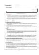
4.2 Logging on to the Switch To log on to the Switch: 1. At the screen prompt: Figure 4-1 SGSW-2402 Console Login on Screen Enter the console interface factory default console password (admin) or user-defined password if you changed the default password using the instructions in Section 4.2.9 .
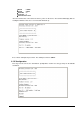
Please type “Help” on the command line, the main menu displays all the system command usage that are available as below: Figure 4-3 SGSW-2402 Console command Screen SYS--SYSTEM MANAGEMENT COMMANDS sys show info sys show ip sys show ethernet address sys set ip sys set name "string" sys set contact "string" sys set location "string" sys set password sys set link_info sys reset system sys reset config sys save config LOGOUT--EXIT MANAGEMENT COMMANDS Logou
VLAN--VLAN MANAGEMENT COMMANDS vlan show vlan build <-u untags> <-t tags> <-p priority> vlan delete vlan set pri <-p priority> TRUNK--TRUNK MANAGEMENT COMMANDS trunk show trunk set [port2] [port3] [port4] STP--STP MANAGEMENT COMMANDS stp [on|off] SNMP--SNMP MANAGEMENT COMMANDS SNMP [ON|OFF] STACK--STACK MANAGEMENT COMMANDS stack [on|off] 4.2.1. sys--System Management Commands This menu contains system parameters to display and configure the switch to your network.
4.2.2 sys show info This command display the system information of SGSW-2402. Figure 4-5 SGSW-2402 system information Screen 4.2.3. sys show IP This command display the network information of SGSW-2402.
4.2.4. sys show Ethernet address This command display the MAC address of SGSW-2402. Figure 4-7 SGSW-2402 Mac address information Screen 4.2.5. sys set ip This command allow to set the IP address, Subnet Mask, Gateway of SGSW-2402.
4.2.6. sys set name "string" This commands allow to set the system name of SGSW-2402. Figure 4-9 SGSW-2402 system name setting Screen 4.2.7. sys set contact "string" This command allow to set system administrator name of SGSW-2402.
4.2.8. sys set location "string" This command allow to set the location of SGSW-2402. Figure 4-11 SGSW-2402 system location setting Screen 4.2.9. sys set password This command allow to set the password of SGSW-2402.
4.2.10. sys set link_info This command is used to report the link status of the ports. Once it is enabled, it will prompt the port status on the console. Or if you disable it, it will not prompt the port status any more. Figure 4-13 SGSW-2402 system link report setting Screen 4.2.11. sys reset system This command will reboot the SGSW-2402.
4.2.12. sys reset config This command will reboot and reset to the default mode of SGSW-2402. Figure 4-15 SGSW-2402 reset config Screen 4.2.13. sys save config This command will save the current configure of SGSW-2402.
4.2.14. logout This command will logout the SGSW-2402. Figure 4-17 SGSW-2402 logout Screen 4.2.15.
4.2.16. port show This command display port status of each port. Figure 4-19 SGSW-2402 port statistics Screen 4.2.17.
4.2.18. port set disable This command allow to disable each port Figure 4-21 SGSW-2402 port disable Screen 4.2.19. port set flw This command allow to disable or enable flow control on each port Figure 4-22 SGSW-2402 flow control disable /enable Screen 4.2.20.
4.2.21. port set pri <-p priority> This command allow to set the priority on each port Figure 4-24 SGSW-2402 port priority Screen 4.2.22. port set vid <-v vid> This command allow to set the VLAN group and assign VLAN ID.
4.2.23. vlan--VLAN Management Commands This menu contains system parameters to display and configure the VLAN of SGSW-2402 . Menu items are: Figure 4-25 SGSW-2402 VLAN command Screen 4.2.24.
4.2.25. vlan build <-u untags> <-t tags> <-p priority> This command allow to create VLAN group and assign VLAN tag and untagged Figure 4-27 SGSW-2402 VLAN setting Screen 4.2.26. vlan delete This command allow to delete VLAN group. Figure 4-28 SGSW-2402 VLAN delete Screen 4.2.27. vlan set pri <-p priority> This command allow to set VLAN priority.
4.2.28. trunk--TRUNK Management Commands This menu contains system parameters to display and configure the trunk of this switch. Menu items are: Figure 4-29 SGSW-2402 Trunk command Screen 4.2.29.
4.2.30. trunk set [port2] [port3] [port4] This command allow to set trunk port Figure 4-31 SGSW-2402 Trunk group setting Screen 4.2.31. stp--STP Management Commands This command allow to disable / enable STP function on SGSW-2402 Figure 4-31 SGSW-2402 disable / enable STP Screen 4.2.32.
4.2.33.
APPENDIX A NETWORKING CONNECTION When attaching an end-station to the device, a standard straight-through CAT5 cable may be used, even when the end-station is attached via a patch panel. However, when attaching another switch or attaching workstations via hubs, a crossover cable will need to be used. Please see the following wire diagrams for examples of both cable types.