
User's Manual


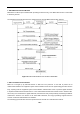


Table Of Contents
- Chapter 1 INTRODUCTION
- Chapter 2 INSTALLATION
- Chapter 3 Switch Management
- Chapter 4 Basic Switch Configuration
- Chapter 5 File System Operations
- Chapter 6 Cluster Configuration
- Chapter 7 Port Configuration
- Chapter 8 Port Isolation Function Configuration
- Chapter 9 Port Loopback Detection Function Configuration
- Chapter 10 ULDP Function Configuration
- Chapter 11 LLDP Function Operation Configuration
- Chapter 12 Port Channel Configuration
- Chapter 13 Jumbo Configuration
- Chapter 14 EFM OAM Configuration
- Chapter 15 VLAN Configuration
- Chapter 16 MAC Table Configuration
- Chapter 17 MSTP Configuration
- Chapter 18 QoS Configuration
- Chapter 19 Flow-based Redirection
- Chapter 20 Egress QoS Configuration
- Chapter 21 Flexible Q-in-Q Configuration
- Chapter 22 Layer 3 Forward Configuration
- Chapter 23 ARP Scanning Prevention Function Configuration
- Chapter 24 Prevent ARP, ND Spoofing Configuration
- Chapter 25 ARP GUARD Configuration
- Chapter 26 ARP Local Proxy Configuration
- Chapter 27 Gratuitous ARP Configuration
- Chapter 28 Keepalive Gateway Configuration
- Chapter 29 DHCP Configuration
- Chapter 30 DHCPv6 Configuration
- Chapter 31 DHCP option 82 Configuration
- Chapter 32 DHCPv6 option37, 38
- Chapter 33 DHCP Snooping Configuration
- Chapter 34 Routing Protocol Overview
- Chapter 35 Static Route
- Chapter 36 RIP
- Chapter 37 RIPng
- Chapter 38 OSPF
- Chapter 39 OSPFv3
- Chapter 40 BGP
- 40.1 Introduction to BGP
- 40.2 BGP Configuration Task List
- 40.3 Configuration Examples of BGP
- 40.3.1 Examples 1: configure BGP neighbor
- 40.3.2 Examples 2: configure BGP aggregation
- 40.3.3 Examples 3: configure BGP community attributes
- 40.3.4 Examples 4: configure BGP confederation
- 40.3.5 Examples 5: configure BGP route reflector
- 40.3.6 Examples 6: configure MED of BGP
- 40.3.7 Examples 7: example of BGP VPN
- 40.4 BGP Troubleshooting
- Chapter 41 MBGP4+
- Chapter 42 Black Hole Routing Manual
- Chapter 43 GRE Tunnel Configuration
- Chapter 44 ECMP Configuration
- Chapter 45 BFD
- Chapter 46 BGP GR
- Chapter 47 OSPF GR
- Chapter 48 IPv4 Multicast Protocol
- 48.1 IPv4 Multicast Protocol Overview
- 48.2 PIM-DM
- 48.3 PIM-SM
- 48.4 MSDP Configuration
- 48.4.1 Introduction to MSDP
- 48.4.2 Brief Introduction to MSDP Configuration Tasks
- 48.4.3 Configuration of MSDP Basic Function
- 48.4.4 Configuration of MSDP Entities
- 48.4.5 Configuration of Delivery of MSDP Packet
- 48.4.6 Configuration of Parameters of SA-cache
- 48.4.7 MSDP Configuration Examples
- 48.4.8 MSDP Troubleshooting
- 48.5 ANYCAST RP Configuration
- 48.6 PIM-SSM
- 48.7 DVMRP
- 48.8 DCSCM
- 48.9 IGMP
- 48.10 IGMP Snooping
- 48.11 IGMP Proxy Configuration
- Chapter 49 IPv6 Multicast Protocol
- Chapter 50 Multicast VLAN
- Chapter 51 ACL Configuration
- Chapter 52 802.1x Configuration
- 52.1 Introduction to 802.1x
- 52.2 802.1x Configuration Task List
- 52.3 802.1x Application Example
- 52.4 802.1x Troubleshooting
- Chapter 53 The Number Limitation Function of Port, MAC in VLAN and IP Configuration
- 53.1 Introduction to the Number Limitation Function of Port, MAC in VLAN and IP
- 53.2 The Number Limitation Function of Port, MAC in VLAN and IP Configuration Task Sequence
- 53.3 The Number Limitation Function of Port, MAC in VLAN and IP Typical Examples
- 53.4 The Number Limitation Function of Port, MAC in VLAN and IP Troubleshooting Help
- Chapter 54 Operational Configuration of AM Function
- Chapter 55 TACACS+ Configuration
- Chapter 56 RADIUS Configuration
- Chapter 57 SSL Configuration
- Chapter 58 IPv6 Security RA Configuration
- Chapter 59 VLAN-ACL Configuration
- Chapter 60 MAB Configuration
- Chapter 61 PPPoE Intermediate Agent Configuration
- Chapter 62 SAVI Configuration
- Chapter 63 Web Portal Configuration
- Chapter 64 VRRP Configuration
- Chapter 65 IPv6 VRRPv3 Configuration
- Chapter 66 MRPP Configuration
- Chapter 67 ULPP Configuration
- Chapter 68 ULSM Configuration
- Chapter 69 Mirror Configuration
- Chapter 70 RSPAN Configuration
- Chapter 71 sFlow Configuration
- Chapter 72 SNTP Configuration
- Chapter 73 NTP Function Configuration
- Chapter 74 DNSv4/v6 Configuration
- Chapter 75 Summer Time Configuration
- Chapter 76 Monitor and Debug
- Chapter 77 Reload Switch after Specified Time
- Chapter 78 Debugging and Diagnosis for Packets Received and Sent by CPU
- Chapter 79 VSF
- Chapter 80 PoE Configuration
- Chapter 81 SWITCH OPERATION
- Chapter 82 TROUBLESHOOTING
- Chapter 83 APPENDIX A
- Chapter 84 GLOSSARY

52-2
system should support EAPOL (Extensible Authentication Protocol over LAN).
The authenticator system is another entity on one end of the LAN segment to authenticate the
supplicant systems connected. An authenticator system usually is a network device supporting
802,1x protocol, providing ports to access the LAN for supplicant systems. The ports provided can
either be physical or logical.
The authentication server system is an entity to provide authentication service for authenticator
systems. The authentication server system is used to authenticate and authorize users, as well as
does fee-counting, and usually is a RADIUS (Remote Authentication Dial-In User Service) server,
which can store the relative user information, including username, password and other parameters
such as the VLAN and ports which the user belongs to.
The three entities above concerns the following basic concepts: PAE of the port, the controlled ports and the
controlled direction.
1. PAE
PAE (Port Access Entity) is the entity to implement the operation of algorithms and protocols.
The PAE of the supplicant system is supposed to respond the authentication request from the
authenticator systems and submit user’s authentication information to the authenticator system. It
can also send authentication request and off-line request to authenticator.
The PAE of the authenticator system authenticates the supplicant systems needing to access the
LAN via the authentication server system, and deal with the authenticated/unauthenticated state of
the controlled port according to the result of the authentication. The authenticated state means the
user is allowed to access the network resources, the unauthenticated state means only the EAPOL
messages are allowed to be received and sent while the user is forbidden to access network
resources.
2. controlled/uncontrolled ports
The authenticator system provides ports to access the LAN for the supplicant systems. These ports can be
divided into two kinds of logical ports: controlled ports and uncontrolled ports.
The uncontrolled port is always in bi-directionally connected status, and mainly used to transmit
EAPOL protocol frames, to guarantee that the supplicant systems can always send or receive
authentication messages.
The controlled port is in connected status authenticated to transmit service messages. When
unauthenticated, no message from supplicant systems is allowed to be received.
The controlled and uncontrolled ports are two parts of one port, which means each frame reaching
this port is visible on both the controlled and uncontrolled ports.
3. Controlled direction
In unauthenticated status, controlled ports can be set as unidirectional controlled or bi-directionally controlled.
When the port is bi-directionally controlled, the sending and receiving of all frames is forbidden.
When the port is unidirectional controlled, no frames can be received from the supplicant systems
while sending frames to the supplicant systems is allowed.
Notes: At present, this kind of switch only supports unidirectional control.