
User's Manual


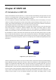
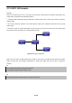


Table Of Contents
- Chapter 1 INTRODUCTION
- Chapter 2 INSTALLATION
- Chapter 3 Switch Management
- Chapter 4 Basic Switch Configuration
- Chapter 5 File System Operations
- Chapter 6 Cluster Configuration
- Chapter 7 Port Configuration
- Chapter 8 Port Isolation Function Configuration
- Chapter 9 Port Loopback Detection Function Configuration
- Chapter 10 ULDP Function Configuration
- Chapter 11 LLDP Function Operation Configuration
- Chapter 12 Port Channel Configuration
- Chapter 13 Jumbo Configuration
- Chapter 14 EFM OAM Configuration
- Chapter 15 VLAN Configuration
- Chapter 16 MAC Table Configuration
- Chapter 17 MSTP Configuration
- Chapter 18 QoS Configuration
- Chapter 19 Flow-based Redirection
- Chapter 20 Egress QoS Configuration
- Chapter 21 Flexible Q-in-Q Configuration
- Chapter 22 Layer 3 Forward Configuration
- Chapter 23 ARP Scanning Prevention Function Configuration
- Chapter 24 Prevent ARP, ND Spoofing Configuration
- Chapter 25 ARP GUARD Configuration
- Chapter 26 ARP Local Proxy Configuration
- Chapter 27 Gratuitous ARP Configuration
- Chapter 28 Keepalive Gateway Configuration
- Chapter 29 DHCP Configuration
- Chapter 30 DHCPv6 Configuration
- Chapter 31 DHCP option 82 Configuration
- Chapter 32 DHCPv6 option37, 38
- Chapter 33 DHCP Snooping Configuration
- Chapter 34 Routing Protocol Overview
- Chapter 35 Static Route
- Chapter 36 RIP
- Chapter 37 RIPng
- Chapter 38 OSPF
- Chapter 39 OSPFv3
- Chapter 40 BGP
- 40.1 Introduction to BGP
- 40.2 BGP Configuration Task List
- 40.3 Configuration Examples of BGP
- 40.3.1 Examples 1: configure BGP neighbor
- 40.3.2 Examples 2: configure BGP aggregation
- 40.3.3 Examples 3: configure BGP community attributes
- 40.3.4 Examples 4: configure BGP confederation
- 40.3.5 Examples 5: configure BGP route reflector
- 40.3.6 Examples 6: configure MED of BGP
- 40.3.7 Examples 7: example of BGP VPN
- 40.4 BGP Troubleshooting
- Chapter 41 MBGP4+
- Chapter 42 Black Hole Routing Manual
- Chapter 43 GRE Tunnel Configuration
- Chapter 44 ECMP Configuration
- Chapter 45 BFD
- Chapter 46 BGP GR
- Chapter 47 OSPF GR
- Chapter 48 IPv4 Multicast Protocol
- 48.1 IPv4 Multicast Protocol Overview
- 48.2 PIM-DM
- 48.3 PIM-SM
- 48.4 MSDP Configuration
- 48.4.1 Introduction to MSDP
- 48.4.2 Brief Introduction to MSDP Configuration Tasks
- 48.4.3 Configuration of MSDP Basic Function
- 48.4.4 Configuration of MSDP Entities
- 48.4.5 Configuration of Delivery of MSDP Packet
- 48.4.6 Configuration of Parameters of SA-cache
- 48.4.7 MSDP Configuration Examples
- 48.4.8 MSDP Troubleshooting
- 48.5 ANYCAST RP Configuration
- 48.6 PIM-SSM
- 48.7 DVMRP
- 48.8 DCSCM
- 48.9 IGMP
- 48.10 IGMP Snooping
- 48.11 IGMP Proxy Configuration
- Chapter 49 IPv6 Multicast Protocol
- Chapter 50 Multicast VLAN
- Chapter 51 ACL Configuration
- Chapter 52 802.1x Configuration
- 52.1 Introduction to 802.1x
- 52.2 802.1x Configuration Task List
- 52.3 802.1x Application Example
- 52.4 802.1x Troubleshooting
- Chapter 53 The Number Limitation Function of Port, MAC in VLAN and IP Configuration
- 53.1 Introduction to the Number Limitation Function of Port, MAC in VLAN and IP
- 53.2 The Number Limitation Function of Port, MAC in VLAN and IP Configuration Task Sequence
- 53.3 The Number Limitation Function of Port, MAC in VLAN and IP Typical Examples
- 53.4 The Number Limitation Function of Port, MAC in VLAN and IP Troubleshooting Help
- Chapter 54 Operational Configuration of AM Function
- Chapter 55 TACACS+ Configuration
- Chapter 56 RADIUS Configuration
- Chapter 57 SSL Configuration
- Chapter 58 IPv6 Security RA Configuration
- Chapter 59 VLAN-ACL Configuration
- Chapter 60 MAB Configuration
- Chapter 61 PPPoE Intermediate Agent Configuration
- Chapter 62 SAVI Configuration
- Chapter 63 Web Portal Configuration
- Chapter 64 VRRP Configuration
- Chapter 65 IPv6 VRRPv3 Configuration
- Chapter 66 MRPP Configuration
- Chapter 67 ULPP Configuration
- Chapter 68 ULSM Configuration
- Chapter 69 Mirror Configuration
- Chapter 70 RSPAN Configuration
- Chapter 71 sFlow Configuration
- Chapter 72 SNTP Configuration
- Chapter 73 NTP Function Configuration
- Chapter 74 DNSv4/v6 Configuration
- Chapter 75 Summer Time Configuration
- Chapter 76 Monitor and Debug
- Chapter 77 Reload Switch after Specified Time
- Chapter 78 Debugging and Diagnosis for Packets Received and Sent by CPU
- Chapter 79 VSF
- Chapter 80 PoE Configuration
- Chapter 81 SWITCH OPERATION
- Chapter 82 TROUBLESHOOTING
- Chapter 83 APPENDIX A
- Chapter 84 GLOSSARY

47-16
Chapter 47 OSPF GR
47.1 Introduction to OSPF GR
OSPF Graceful-Restart(short for OSPF GR), is used to maintain data forwarding correctly and flow of crucial
service is not interrupted when routing protocol restarts or switchover of layer 3 switches between active
master and standby master. It is one of high availability technologies.
So far, the high layer 3 switches usually adopt a design for separating control and forwarding. The control
module for counting routing protocol at master control board, but data forwarding module is at liner card. As a
result, it will not affect data forwarding on line card when the master control board is restarted. So the device
supporting GR is generally a chassis device and has two master control boards.
Since standard OSPF protocol (RFC2328) does not support GR, it will lead to flow cut off and routing surge
when routing protocol is restarted or switchover between active master and standby master for various
reasons. For example, as shown in below figure, when S1 occurs switchover, the neighborhood relation
between S1 and S2 will lose, at that time S2 will send Router-LSA to S3 and S4 and this LSA does not include
the link between S1 and S2. After S3 and S4 received LSA, they will count routing protocol again. The result
will not include the link between S1 and S2. After S1 finishes the switchover, it will establish neighborhood
relation with S2 and synchronize database, this action leads S2, S3 and S4 to count routing again. However,
switchover of S1 will result routing shiver, which is not accepted by some networks with high requirement for
performance.
S1
S2
S3
S4
Figure 47-1 typical application scene
OSPF GR described in RF C3623 is come up for the above state. Its basic idea is that if the network topology
keeps stabilization during the switchover and layer 3 switch can maintain the same forwarding list, then its
neighbor can maintain their relationship, which can make the switch on its forwarding path still. If S1 and S2
support and enable GR, the liner card of S1 will keep the traffic forwarding and S2 can maintain the
relationship with S1, at the same time, network topology between S3 and S4 will not be changed, furthermore,
it does not need to count routing again. All of these ensure the traffic forwarding and avoid routing shiver.
Layer 3 switch can be divided into GR restarter and GR helper according to its function in GR process. GR
restarter is layer 3 switch to occur the switchover between active master and standby master or restart