
User's Manual


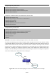


Table Of Contents
- Chapter 1 INTRODUCTION
- Chapter 2 INSTALLATION
- Chapter 3 Switch Management
- Chapter 4 Basic Switch Configuration
- Chapter 5 File System Operations
- Chapter 6 Cluster Configuration
- Chapter 7 Port Configuration
- Chapter 8 Port Isolation Function Configuration
- Chapter 9 Port Loopback Detection Function Configuration
- Chapter 10 ULDP Function Configuration
- Chapter 11 LLDP Function Operation Configuration
- Chapter 12 Port Channel Configuration
- Chapter 13 Jumbo Configuration
- Chapter 14 EFM OAM Configuration
- Chapter 15 VLAN Configuration
- Chapter 16 MAC Table Configuration
- Chapter 17 MSTP Configuration
- Chapter 18 QoS Configuration
- Chapter 19 Flow-based Redirection
- Chapter 20 Egress QoS Configuration
- Chapter 21 Flexible Q-in-Q Configuration
- Chapter 22 Layer 3 Forward Configuration
- Chapter 23 ARP Scanning Prevention Function Configuration
- Chapter 24 Prevent ARP, ND Spoofing Configuration
- Chapter 25 ARP GUARD Configuration
- Chapter 26 ARP Local Proxy Configuration
- Chapter 27 Gratuitous ARP Configuration
- Chapter 28 Keepalive Gateway Configuration
- Chapter 29 DHCP Configuration
- Chapter 30 DHCPv6 Configuration
- Chapter 31 DHCP option 82 Configuration
- Chapter 32 DHCPv6 option37, 38
- Chapter 33 DHCP Snooping Configuration
- Chapter 34 Routing Protocol Overview
- Chapter 35 Static Route
- Chapter 36 RIP
- Chapter 37 RIPng
- Chapter 38 OSPF
- Chapter 39 OSPFv3
- Chapter 40 BGP
- 40.1 Introduction to BGP
- 40.2 BGP Configuration Task List
- 40.3 Configuration Examples of BGP
- 40.3.1 Examples 1: configure BGP neighbor
- 40.3.2 Examples 2: configure BGP aggregation
- 40.3.3 Examples 3: configure BGP community attributes
- 40.3.4 Examples 4: configure BGP confederation
- 40.3.5 Examples 5: configure BGP route reflector
- 40.3.6 Examples 6: configure MED of BGP
- 40.3.7 Examples 7: example of BGP VPN
- 40.4 BGP Troubleshooting
- Chapter 41 MBGP4+
- Chapter 42 Black Hole Routing Manual
- Chapter 43 GRE Tunnel Configuration
- Chapter 44 ECMP Configuration
- Chapter 45 BFD
- Chapter 46 BGP GR
- Chapter 47 OSPF GR
- Chapter 48 IPv4 Multicast Protocol
- 48.1 IPv4 Multicast Protocol Overview
- 48.2 PIM-DM
- 48.3 PIM-SM
- 48.4 MSDP Configuration
- 48.4.1 Introduction to MSDP
- 48.4.2 Brief Introduction to MSDP Configuration Tasks
- 48.4.3 Configuration of MSDP Basic Function
- 48.4.4 Configuration of MSDP Entities
- 48.4.5 Configuration of Delivery of MSDP Packet
- 48.4.6 Configuration of Parameters of SA-cache
- 48.4.7 MSDP Configuration Examples
- 48.4.8 MSDP Troubleshooting
- 48.5 ANYCAST RP Configuration
- 48.6 PIM-SSM
- 48.7 DVMRP
- 48.8 DCSCM
- 48.9 IGMP
- 48.10 IGMP Snooping
- 48.11 IGMP Proxy Configuration
- Chapter 49 IPv6 Multicast Protocol
- Chapter 50 Multicast VLAN
- Chapter 51 ACL Configuration
- Chapter 52 802.1x Configuration
- 52.1 Introduction to 802.1x
- 52.2 802.1x Configuration Task List
- 52.3 802.1x Application Example
- 52.4 802.1x Troubleshooting
- Chapter 53 The Number Limitation Function of Port, MAC in VLAN and IP Configuration
- 53.1 Introduction to the Number Limitation Function of Port, MAC in VLAN and IP
- 53.2 The Number Limitation Function of Port, MAC in VLAN and IP Configuration Task Sequence
- 53.3 The Number Limitation Function of Port, MAC in VLAN and IP Typical Examples
- 53.4 The Number Limitation Function of Port, MAC in VLAN and IP Troubleshooting Help
- Chapter 54 Operational Configuration of AM Function
- Chapter 55 TACACS+ Configuration
- Chapter 56 RADIUS Configuration
- Chapter 57 SSL Configuration
- Chapter 58 IPv6 Security RA Configuration
- Chapter 59 VLAN-ACL Configuration
- Chapter 60 MAB Configuration
- Chapter 61 PPPoE Intermediate Agent Configuration
- Chapter 62 SAVI Configuration
- Chapter 63 Web Portal Configuration
- Chapter 64 VRRP Configuration
- Chapter 65 IPv6 VRRPv3 Configuration
- Chapter 66 MRPP Configuration
- Chapter 67 ULPP Configuration
- Chapter 68 ULSM Configuration
- Chapter 69 Mirror Configuration
- Chapter 70 RSPAN Configuration
- Chapter 71 sFlow Configuration
- Chapter 72 SNTP Configuration
- Chapter 73 NTP Function Configuration
- Chapter 74 DNSv4/v6 Configuration
- Chapter 75 Summer Time Configuration
- Chapter 76 Monitor and Debug
- Chapter 77 Reload Switch after Specified Time
- Chapter 78 Debugging and Diagnosis for Packets Received and Sent by CPU
- Chapter 79 VSF
- Chapter 80 PoE Configuration
- Chapter 81 SWITCH OPERATION
- Chapter 82 TROUBLESHOOTING
- Chapter 83 APPENDIX A
- Chapter 84 GLOSSARY

39-3
In one word, LSA can only be transferred between neighboring Layer3 switches, and OSPFv3 protocol
includes seven kinds of LSA: link LSA, internal-area prefix LSA, router LSA, network LSA, inter-area prefix
LSA, inter-area router LSA and autonomic system exterior LSA. Router LSA is generated by each Layer 3
switch in an OSPF area, and is sent to all other neighboring Layer 3 switch in this area; network LSA is
generated by designated Layer 3 switch in the OSPF area of multi-access network and is sent to all other
neighboring layer3 switches in this area.(To reduce data traffic among each Layer 3 switches in the
multi-access network, “designated layer3 switch” and “backup designated layer3 switch” should be selected in
the multi-access network, and the network link-state is broadcasted by designated Layer 3 switch); the
inter-area prefix LSA and inter-area router LSA are generated by OSPF area border Layer 3 switches and
transferred among those switches. The autonomic system exterior LSA is generated by autonomic system
exterior border Layer 3 switches and transferred in the whole autonomic system. Link LSA is generated by
Layer 3 switch on the link and sent to other Layer 3 switches on the link. Internal-area prefix LSA is generated
by designated layer3 switch of each link in this area, and flooded to the whole area.
For autonomous system focused on exterior link-state announcement, OSPFv3 allow some areas to be
configured as STUB areas in order to reduce the size of topological database. Router LSA, network LSA,
inter-area prefix LSA, link LSA, internal-area prefix LSA are permitted to advertise to STUB area. Default route
must be used in STUB area, Layer 3 switches on the area border of STUB area announces to default routes
of STUB area by inter-area prefix LSA; these default routes only flood in STUB area, not outside of STUB
area. Each STUB area has a corresponding default route, the route from STUB area to AS exterior
destination depends only on default route of this area.
The following simply outlines the route calculation process of OSPFv3 protocol:
1. Each OSPF-enabled layer3 switch maintains a database (LS database) describing the link-state of the
topology structure of the whole autonomous system. Each layer3 switch generates a link-state
advertisement according to its surrounding network topology structure (router LSA), and sends the LSA
to other layer3 switches through link-state update (LSU) packets. Thus, each layer3 switches receives
LSAs from other layer3 switches, and all LSAs combined to the link-state database.
2. Since a LSA is the description of the network topology structure around a layer3 switch, the LS database
is the description of the network topology structure of the whole network. The layer3 switches can easily
create a weighted vector map according to the LS database. Obviously, all layer3 switches in the same
autonomous system will have the same network topology map.
3. Each layer3 switch uses the shortest path first (SPF) algorithm to calculate a tree of shortest path rooted
by itself. The tree provides the route to all the nodes in the autonomous system, leaf nodes consist of the
exterior route information. The exterior route can be marked by the layer3 switch broadcast it, so that
additional information about the autonomous system can be recorded. As a result, the route table of
each layer3 switch is different.
OSPFv3 protocol is developed by the IETF, the OSPF v3 used now is fulfilled according to the content
described in RFC2328 and RFC2740.
As a result of continuous development of IPv6 network, it has the network environment of nonsupport IPv6
sometimes, so it needs to do the IPv6 operation by tunnel. Therefore, our OSPFv3 supports configuration on
configure tunnel, and passes through nonsupport IPv6 network by unicast packet of IPv4 encapsulation.