
User's Manual


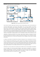
Table Of Contents
- Chapter 1 INTRODUCTION
- Chapter 2 INSTALLATION
- Chapter 3 Switch Management
- Chapter 4 Basic Switch Configuration
- Chapter 5 File System Operations
- Chapter 6 Cluster Configuration
- Chapter 7 Port Configuration
- Chapter 8 Port Isolation Function Configuration
- Chapter 9 Port Loopback Detection Function Configuration
- Chapter 10 ULDP Function Configuration
- Chapter 11 LLDP Function Operation Configuration
- Chapter 12 Port Channel Configuration
- Chapter 13 Jumbo Configuration
- Chapter 14 EFM OAM Configuration
- Chapter 15 VLAN Configuration
- Chapter 16 MAC Table Configuration
- Chapter 17 MSTP Configuration
- Chapter 18 QoS Configuration
- Chapter 19 Flow-based Redirection
- Chapter 20 Egress QoS Configuration
- Chapter 21 Flexible Q-in-Q Configuration
- Chapter 22 Layer 3 Forward Configuration
- Chapter 23 ARP Scanning Prevention Function Configuration
- Chapter 24 Prevent ARP, ND Spoofing Configuration
- Chapter 25 ARP GUARD Configuration
- Chapter 26 ARP Local Proxy Configuration
- Chapter 27 Gratuitous ARP Configuration
- Chapter 28 Keepalive Gateway Configuration
- Chapter 29 DHCP Configuration
- Chapter 30 DHCPv6 Configuration
- Chapter 31 DHCP option 82 Configuration
- Chapter 32 DHCPv6 option37, 38
- Chapter 33 DHCP Snooping Configuration
- Chapter 34 Routing Protocol Overview
- Chapter 35 Static Route
- Chapter 36 RIP
- Chapter 37 RIPng
- Chapter 38 OSPF
- Chapter 39 OSPFv3
- Chapter 40 BGP
- 40.1 Introduction to BGP
- 40.2 BGP Configuration Task List
- 40.3 Configuration Examples of BGP
- 40.3.1 Examples 1: configure BGP neighbor
- 40.3.2 Examples 2: configure BGP aggregation
- 40.3.3 Examples 3: configure BGP community attributes
- 40.3.4 Examples 4: configure BGP confederation
- 40.3.5 Examples 5: configure BGP route reflector
- 40.3.6 Examples 6: configure MED of BGP
- 40.3.7 Examples 7: example of BGP VPN
- 40.4 BGP Troubleshooting
- Chapter 41 MBGP4+
- Chapter 42 Black Hole Routing Manual
- Chapter 43 GRE Tunnel Configuration
- Chapter 44 ECMP Configuration
- Chapter 45 BFD
- Chapter 46 BGP GR
- Chapter 47 OSPF GR
- Chapter 48 IPv4 Multicast Protocol
- 48.1 IPv4 Multicast Protocol Overview
- 48.2 PIM-DM
- 48.3 PIM-SM
- 48.4 MSDP Configuration
- 48.4.1 Introduction to MSDP
- 48.4.2 Brief Introduction to MSDP Configuration Tasks
- 48.4.3 Configuration of MSDP Basic Function
- 48.4.4 Configuration of MSDP Entities
- 48.4.5 Configuration of Delivery of MSDP Packet
- 48.4.6 Configuration of Parameters of SA-cache
- 48.4.7 MSDP Configuration Examples
- 48.4.8 MSDP Troubleshooting
- 48.5 ANYCAST RP Configuration
- 48.6 PIM-SSM
- 48.7 DVMRP
- 48.8 DCSCM
- 48.9 IGMP
- 48.10 IGMP Snooping
- 48.11 IGMP Proxy Configuration
- Chapter 49 IPv6 Multicast Protocol
- Chapter 50 Multicast VLAN
- Chapter 51 ACL Configuration
- Chapter 52 802.1x Configuration
- 52.1 Introduction to 802.1x
- 52.2 802.1x Configuration Task List
- 52.3 802.1x Application Example
- 52.4 802.1x Troubleshooting
- Chapter 53 The Number Limitation Function of Port, MAC in VLAN and IP Configuration
- 53.1 Introduction to the Number Limitation Function of Port, MAC in VLAN and IP
- 53.2 The Number Limitation Function of Port, MAC in VLAN and IP Configuration Task Sequence
- 53.3 The Number Limitation Function of Port, MAC in VLAN and IP Typical Examples
- 53.4 The Number Limitation Function of Port, MAC in VLAN and IP Troubleshooting Help
- Chapter 54 Operational Configuration of AM Function
- Chapter 55 TACACS+ Configuration
- Chapter 56 RADIUS Configuration
- Chapter 57 SSL Configuration
- Chapter 58 IPv6 Security RA Configuration
- Chapter 59 VLAN-ACL Configuration
- Chapter 60 MAB Configuration
- Chapter 61 PPPoE Intermediate Agent Configuration
- Chapter 62 SAVI Configuration
- Chapter 63 Web Portal Configuration
- Chapter 64 VRRP Configuration
- Chapter 65 IPv6 VRRPv3 Configuration
- Chapter 66 MRPP Configuration
- Chapter 67 ULPP Configuration
- Chapter 68 ULSM Configuration
- Chapter 69 Mirror Configuration
- Chapter 70 RSPAN Configuration
- Chapter 71 sFlow Configuration
- Chapter 72 SNTP Configuration
- Chapter 73 NTP Function Configuration
- Chapter 74 DNSv4/v6 Configuration
- Chapter 75 Summer Time Configuration
- Chapter 76 Monitor and Debug
- Chapter 77 Reload Switch after Specified Time
- Chapter 78 Debugging and Diagnosis for Packets Received and Sent by CPU
- Chapter 79 VSF
- Chapter 80 PoE Configuration
- Chapter 81 SWITCH OPERATION
- Chapter 82 TROUBLESHOOTING
- Chapter 83 APPENDIX A
- Chapter 84 GLOSSARY

38-12
Scenario 2: Typical OSPF protocol complex topology.
Figure 38-2 Typical complex OSPF autonomous system
This scenario is a typical complex OSPF autonomous system network topology. Area1 include network N1-N4
and layer3 SwitchA-SwitchD, area2 include network N8-N10, host H1 and layer3 SwitchH, area3 include
N5-N7 and Layer3 SwitchF, SwitchG SwitchA0 and Switch11, and network N8-N10 share a summary route
with host H1(i.e. area3 is defined as a STUB area). Layer3 SwitchA, SwitchB, SwitchD, SwitchE, SwitchG,
SwitchH, Switch12 are in-area Layer3 switches, SwitchC, SwitchD, SwitchF, Switch10 and Switch11 are edge
layer3 switches of the area, SwitchD and SwitchF are edge layer3 switches of the autonomous system.
To area1, Layer3 switches SwitchA and SwitchB are both in-area switches, area edge switches SwitchC and
SwitchD are responsible for reporting distance cost to all destination outside the area, while they are also
responsible for reporting the position of the AS edge Layer3 switches SwitchD and SwitchF, AS exterior
link-state advertisement from SwitchD and SwitchF are flooded throughout the whole autonomous system.
When ASE LSA floods in area 1, those LSAs are included in the area 1 database to get the routes to network
N11 and N15.
In addition, Layer3 SwitchC and SwitchD must summary the topology of area 1 to the backbone area (area 0,
all non-0 areas must be connected via area 0, direct connections are not allowed), and advertise the networks
in area 1 (N1-N4) and the costs from SwitchC and SwitchD to those networks. As the backbone area is
required to keep connected, there must be a virtual link between backbone layer3 Switch10 and Switch11.
The area edge Layer3 switches exchange summary information via the backbone Layer3 switch, each area
edge Layer3 switch listens to the summary information from the other edge layer3 switches.
Virtual link can not only maintain the connectivity of the backbone area, but also strengthen the backbone
area. For example, if the connection between backbone Layer3 SwitchG and Switch10 is cut down, the
backbone area will become in continuous. The backbone area can become more robust by establishing a
virtual link between backbone Layer3 switches SwitchF and Switch10. In addition, the virtual link between
SwitchF and Switch10 provide a short path from area 3 to Layer3 SwitchF.
Area3
Area2
Area1
N3
N1
N8
N5
N6
N9
N10
N4
N2
N15
N14
N7
N11
Area0
SwitchA
SwitchB
SwitchC
SwitchD
SwitchE
SwitchF
SwitchI
SwitchL
SwitchK
SwitchJ
SwitchG
SwitchH
N12
N13