
User's Manual
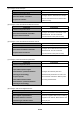
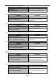


Table Of Contents
- Chapter 1 INTRODUCTION
- Chapter 2 INSTALLATION
- Chapter 3 Switch Management
- Chapter 4 Basic Switch Configuration
- Chapter 5 File System Operations
- Chapter 6 Cluster Configuration
- Chapter 7 Port Configuration
- Chapter 8 Port Isolation Function Configuration
- Chapter 9 Port Loopback Detection Function Configuration
- Chapter 10 ULDP Function Configuration
- Chapter 11 LLDP Function Operation Configuration
- Chapter 12 Port Channel Configuration
- Chapter 13 Jumbo Configuration
- Chapter 14 EFM OAM Configuration
- Chapter 15 VLAN Configuration
- Chapter 16 MAC Table Configuration
- Chapter 17 MSTP Configuration
- Chapter 18 QoS Configuration
- Chapter 19 Flow-based Redirection
- Chapter 20 Egress QoS Configuration
- Chapter 21 Flexible Q-in-Q Configuration
- Chapter 22 Layer 3 Forward Configuration
- Chapter 23 ARP Scanning Prevention Function Configuration
- Chapter 24 Prevent ARP, ND Spoofing Configuration
- Chapter 25 ARP GUARD Configuration
- Chapter 26 ARP Local Proxy Configuration
- Chapter 27 Gratuitous ARP Configuration
- Chapter 28 Keepalive Gateway Configuration
- Chapter 29 DHCP Configuration
- Chapter 30 DHCPv6 Configuration
- Chapter 31 DHCP option 82 Configuration
- Chapter 32 DHCPv6 option37, 38
- Chapter 33 DHCP Snooping Configuration
- Chapter 34 Routing Protocol Overview
- Chapter 35 Static Route
- Chapter 36 RIP
- Chapter 37 RIPng
- Chapter 38 OSPF
- Chapter 39 OSPFv3
- Chapter 40 BGP
- 40.1 Introduction to BGP
- 40.2 BGP Configuration Task List
- 40.3 Configuration Examples of BGP
- 40.3.1 Examples 1: configure BGP neighbor
- 40.3.2 Examples 2: configure BGP aggregation
- 40.3.3 Examples 3: configure BGP community attributes
- 40.3.4 Examples 4: configure BGP confederation
- 40.3.5 Examples 5: configure BGP route reflector
- 40.3.6 Examples 6: configure MED of BGP
- 40.3.7 Examples 7: example of BGP VPN
- 40.4 BGP Troubleshooting
- Chapter 41 MBGP4+
- Chapter 42 Black Hole Routing Manual
- Chapter 43 GRE Tunnel Configuration
- Chapter 44 ECMP Configuration
- Chapter 45 BFD
- Chapter 46 BGP GR
- Chapter 47 OSPF GR
- Chapter 48 IPv4 Multicast Protocol
- 48.1 IPv4 Multicast Protocol Overview
- 48.2 PIM-DM
- 48.3 PIM-SM
- 48.4 MSDP Configuration
- 48.4.1 Introduction to MSDP
- 48.4.2 Brief Introduction to MSDP Configuration Tasks
- 48.4.3 Configuration of MSDP Basic Function
- 48.4.4 Configuration of MSDP Entities
- 48.4.5 Configuration of Delivery of MSDP Packet
- 48.4.6 Configuration of Parameters of SA-cache
- 48.4.7 MSDP Configuration Examples
- 48.4.8 MSDP Troubleshooting
- 48.5 ANYCAST RP Configuration
- 48.6 PIM-SSM
- 48.7 DVMRP
- 48.8 DCSCM
- 48.9 IGMP
- 48.10 IGMP Snooping
- 48.11 IGMP Proxy Configuration
- Chapter 49 IPv6 Multicast Protocol
- Chapter 50 Multicast VLAN
- Chapter 51 ACL Configuration
- Chapter 52 802.1x Configuration
- 52.1 Introduction to 802.1x
- 52.2 802.1x Configuration Task List
- 52.3 802.1x Application Example
- 52.4 802.1x Troubleshooting
- Chapter 53 The Number Limitation Function of Port, MAC in VLAN and IP Configuration
- 53.1 Introduction to the Number Limitation Function of Port, MAC in VLAN and IP
- 53.2 The Number Limitation Function of Port, MAC in VLAN and IP Configuration Task Sequence
- 53.3 The Number Limitation Function of Port, MAC in VLAN and IP Typical Examples
- 53.4 The Number Limitation Function of Port, MAC in VLAN and IP Troubleshooting Help
- Chapter 54 Operational Configuration of AM Function
- Chapter 55 TACACS+ Configuration
- Chapter 56 RADIUS Configuration
- Chapter 57 SSL Configuration
- Chapter 58 IPv6 Security RA Configuration
- Chapter 59 VLAN-ACL Configuration
- Chapter 60 MAB Configuration
- Chapter 61 PPPoE Intermediate Agent Configuration
- Chapter 62 SAVI Configuration
- Chapter 63 Web Portal Configuration
- Chapter 64 VRRP Configuration
- Chapter 65 IPv6 VRRPv3 Configuration
- Chapter 66 MRPP Configuration
- Chapter 67 ULPP Configuration
- Chapter 68 ULSM Configuration
- Chapter 69 Mirror Configuration
- Chapter 70 RSPAN Configuration
- Chapter 71 sFlow Configuration
- Chapter 72 SNTP Configuration
- Chapter 73 NTP Function Configuration
- Chapter 74 DNSv4/v6 Configuration
- Chapter 75 Summer Time Configuration
- Chapter 76 Monitor and Debug
- Chapter 77 Reload Switch after Specified Time
- Chapter 78 Debugging and Diagnosis for Packets Received and Sent by CPU
- Chapter 79 VSF
- Chapter 80 PoE Configuration
- Chapter 81 SWITCH OPERATION
- Chapter 82 TROUBLESHOOTING
- Chapter 83 APPENDIX A
- Chapter 84 GLOSSARY

22-44
22.2.4 IP Configuration Examples
The router lifespan configured should not be smaller than the Send Router advertisement Interval. If the
connected PC has not obtained IPv6 address, you should check RA announcement switch (the default
is turned off).
22.3 IP Forwarding
22.3.1 Introduction to IP Forwarding
Gateway devices can forward IP packets from one subnet to another; such forwarding uses routes to find a
path. IP forwarding of switch is done with the participation of hardware, and can achieve wire speed
forwarding. In addition, flexible management is provided to adjust and monitor forwarding. Switch supports
aggregation algorithm enabling/disabling optimization to adjust generation of network route entry in the switch
chip and view statistics for IP forwarding and hardware forwarding chip status.
22.3.2 IP Route Aggregation Configuration Task
IP route aggregation configuration task:
1. Set whether IP route aggregation algorithm with/without optimization should be used
1. Set whether IP route aggregation algorithm with/without optimization should be used
Command
Explanation
Global Mode
ip fib optimize
no ip fib optimize
Enables the switch to use optimized IP
route aggregation algorithm; the “no ip fib
optimize” disables the optimized IP route
aggregation algorithm.
22.4 URPF
22.4.1 Introduction to URPF
URPF (Unicast Reverse Path Forwarding) introduces the RPF technology applied in multicast to unicast, so
to protect the network from the attacks which is based on source address cheat.
When switch receives the packet, it will search the route in the route table using the source address as the
destination address which is acquired from the packet. If the found router exit interface does not match the
entrance interface acquired from this packet, the switch will consider this packet a fake packet and discard it.
In Source Address Spoofing attacks, attackers will construct a series of messages with fake source addresses.